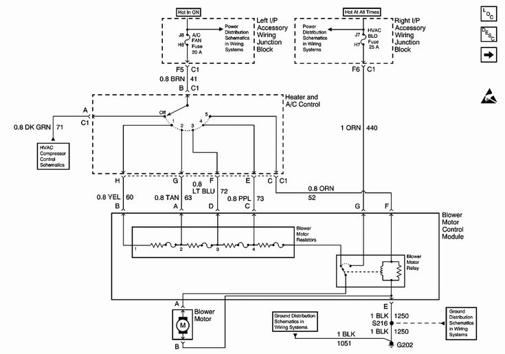
2004 Impala Ignition Wiring Diagram – We will first look at the various types of terminals for the ignition switch. These terminals are used for the Ignition button, Coil and Accessory. Once we know what these kinds of terminals are used for then we can discover the various components of the 2004 Impala Ignition Wiring Diagram. We’ll also discuss the functions as well as the Coil. Then, we’ll focus on the accessory terminals.
Terminals for ignition switches
The ignition switch is comprised of three switches that supply the battery’s current to different destinations. The first one is used to power the choke by pushing it. Then, another switch controls the ON/OFF position. Different manufacturers have different color-coding systems for different conductors. We will cover this in another article. OMC employs this system. An adapter is included on the ignition switch that allows the addition of the tonometer.
While some ignition switch terminals do not have the original design however, the numbers may not be in line with the diagram. To make sure that the wires are properly connected to the switch, it is recommended to check their continuity. This can be done with a multimeter that is inexpensive. Once you are satisfied with the integrity of the wires, it is time to connect the new connector. If you are using a factory-supplied ignition switch the wiring loom will be distinct from the one that is you have in your car.
Knowing how the ACC outputs are connected to the other outputs of your car is essential. The ACC and IGN connectors are the default connections of the ignition switch. The START, IGN, and ACC terminals are primary connections for radios or stereo, the START/IGN connections are the main ones. The ignition switch’s function is to turn the engine of your car on and off. The ignition switch terminals on older vehicles are marked with the alphabets “ACC” as well as “ST” (for individual magneto wires).
Terminals for coil
The first step in determining the kind of ignition coil is to understand the terms that is used. A basic ignition wiring diagram will show a variety of terminals and connections including two primary and two secondaries. Each coil has an operating voltage. The first step to determine the kind of coil you have is to check the voltage on S1, or the primary terminal. S1 should be checked for resistance to identify if the coil belongs to type A, B and/or C.
The chassis’ negative needs to be connected to the low-tension side. This is the ground on the wiring diagram for ignition. The high-tension side delivers positive directly to the spark plugs. The metal body of the coil needs to be connected to the chassis to prevent it from being smothered however it isn’t electrically necessary. The wiring diagram will also illustrate the connection between the positive and negative coils. Sometimes, a malfunctioning ignition coil can be identified by a scan done at an auto parts shop.
The black-and-white-striped wire from the harness goes to the negative terminal. The positive terminal receives the other white wire, which has an trace in black. The black wire is connected to the contactbreaker. If you’re unsure of the connection between the two, try using an old paper clip to take them from the plug housing. It’s also essential to make sure the terminals aren’t bent.
Accessory terminals
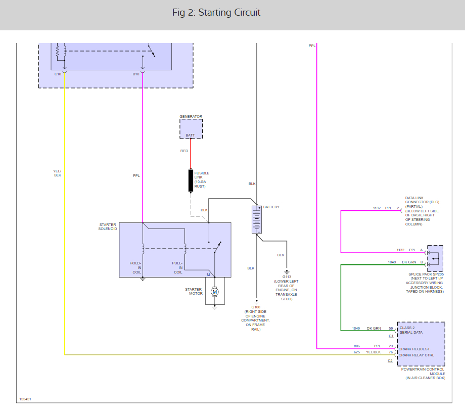
The diagrams for ignition wiring show the wires that are used in the power supply of the vehicle. In general there are four distinct color-coded terminals for each component. Red refers to accessories, yellow the battery, and green is the starter solenoid. The “IGN” terminal is used to start the car , and also to operate the wipers, as well as other operating functions. This diagram demonstrates how to connect ACC and ST terminals to the rest of the components.
The terminal BAT is the connection for the battery. Without the battery, the electrical system does not begin. The switch won’t be able to turn on if the battery isn’t present. The wiring diagram will show the location of your car’s battery. The accessory terminals in your vehicle are connected to the battery as well as the ignition button. The BAT Terminal is connected to the battery.
Certain ignition switches come with the “accessory” setting that permits users to control their outputs without needing to turn on the ignition. Sometimes, users want to utilize an additional output that is independent of the ignition. In order to use the auxiliary output, connect the connector in the same colors as ignition connecting it to the ACC terminal on the switch. This is a great option, but there’s one important distinction. Some ignition switches are configured to be in an ACC position when the vehicle has been moved into the ACC position. They’ll also be in the START mode once the vehicle is moved into the IGN position.
Gallery of 2004 Impala Ignition Wiring Diagram

Gallery of 2004 Impala Ignition Wiring Diagram


