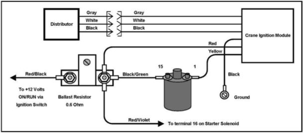
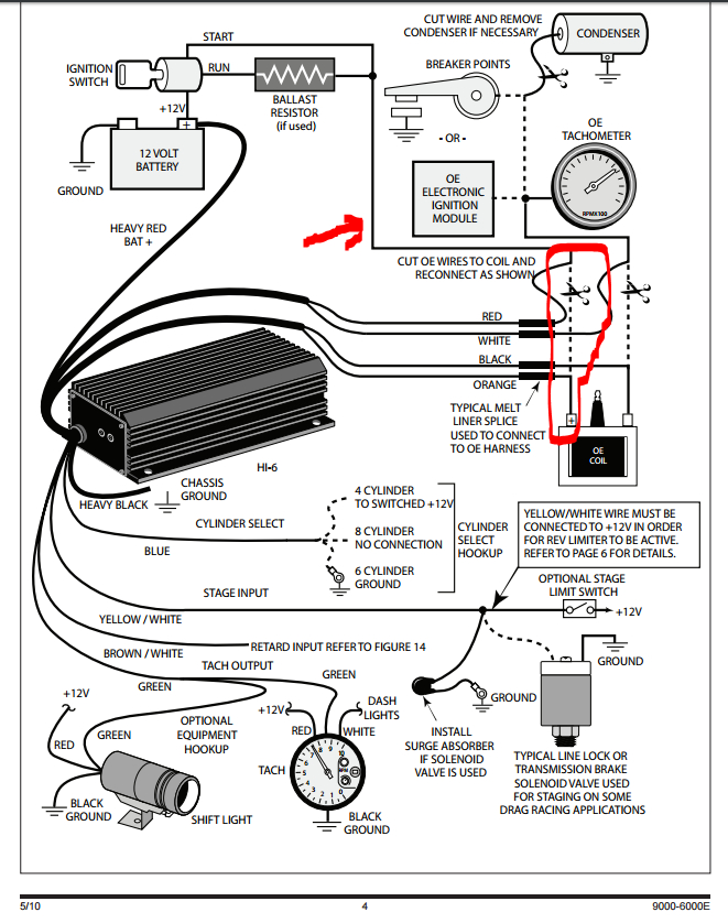
Crane Fireball Hi-6r Ignition Wiring Diagram – The first step is to take a look at the different kinds of terminals for the ignition switch. These terminals serve for the Ignition button, Coil and Accessory. Once we know what these terminals do, we will determine the various components in the ignition wiring. We’ll also discuss the roles of the Ignition switch, as well as the Coil. Then we’ll move on to the Accessory Terminals.
Terminals for the ignition switch
There are three different switches in an ignition switch, which provide the battery’s voltage to a variety of places. The first one is utilized to power the choke by pushing it. Then, another switch controls the ON/OFF position. Different manufacturers use different color-coding methods for different conductors. This will be covered in a separate article. OMC follows this system. The adapter is attached to the ignition switch to allow the addition of the Tachometer.
While the majority of ignition switch terminals don’t have an original number, they may be equipped with a different number. Before plugging into the ignition switch be sure to test the continuity. This can be accomplished using a cheap multimeter. After you’re satisfied with the connection it’s time to connect the new connector. The wiring loom in a factory-supplied ignition system switch is different.
The first step is to understand the distinctions between the ACC and the auxiliary outputs. The ACC and IGN terminals are the default connection on your ignition switch, and the START and IGN terminals are the principal connections to the radio and stereo. The ignition switch’s function is to turn the car’s engines on and off. The terminals of older vehicles’ ignition switches are labeled with “ACC” as well as ST (for individual magneto wires).
Coil terminals
To identify the kind of ignition coil, the initial step is to learn the terms. A simple diagram of the wiring will show a variety of terminals and connections including two primary and two secondary. Each coil is operating at a certain voltage. The first step in determining which type you’re using is to examine the voltage of S1 or the primary terminal. S1 should be checked for resistance to identify if the coil belongs to Type A, B, or C.
The low-tension side of the coil should be connected to the chassis’ negative. This is also the ground in the diagram of ignition wiring. The high-tension component provides the spark plugs with positive. To reduce the noise the body of the coil must be connected to the chassis. However, it is not necessary to connect the coil electrically. The diagram for the ignition wiring will also reveal the connection of the positive and negative coil’s terminals. Sometimes, an inspection at an auto parts shop can diagnose a malfunctioning ignition wire.
The black-and-white-striped wire from the harness goes to the negative terminal. The terminal that is negative is served by the trace in black that’s attached to the white wire. The black wire is connected to the contact breaker. If you’re not certain about the connection between the twowires, use an old paper clip to take them from the housing of the plug. Be sure that you don’t bend the connectors.
Accessory terminals
Diagrams of ignition wiring illustrate the wires that power various parts of the vehicle. Each part has four distinct color-coded connections. The accessories are red, the battery is yellow, and the starter solenoid green. The “IGN” terminal is used to start the car, controlling the wipers and other functions. The diagram shows how you can connect the ACC and ST terminals to the other components.
The terminal called BAT is the place where the battery is. The battery is essential for the electrical system to begin. Additionally, the switch doesn’t turn on. If you don’t know where your car’s battery is situated, look at your wiring diagram to figure out the best way to find it. The accessory terminals of your car connect to the battery and the ignition switch. The BAT terminal is connected to the battery.
Some ignition switches offer an additional “accessory position” that allows users to modify their outputs independent of the ignition. Sometimes, customers want to make use of an additional output that is not connected to the ignition. The auxiliary output can be used by wiring the connector with the same colors as the ignition and attaching it to the ACC terminal of the switch. Although this is a useful feature, there is one important difference. Most ignition switches will have an ACC position if the car is in ACC however, they’ll be at the START position when the car is in IGN.
Gallery of Crane Fireball Hi-6r Ignition Wiring Diagram
Gallery of Crane Fireball Hi-6r Ignition Wiring Diagram


