Boat Ignition Switch Wiring Diagram – The first step is to take a look at the different kinds of terminals for the ignition switch. These terminals comprise the Ignition switch, the Coil along with the Accessory. Once we know the purpose of each terminal, we are able to identify the parts of the ignition wiring. We’ll also discuss the roles of the Ignition switch, and Coil. After that, we’ll turn our attention to Accessory terminals.
Ignition switch terminals
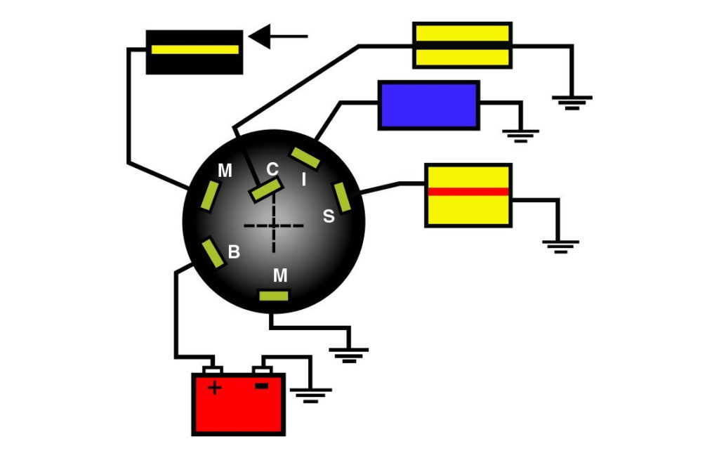
Three switches are found on an ignition switch. Each of the three switches feeds the battery’s voltage to various places. The first one supplies the choke with power when it is pushed. The third is the switch that controls the ignition’s ON/OFF positions. Different manufacturers have different color-coding schemes to identify different conductors. We will cover this in a separate article. OMC uses this method. The ignition switch comes with a connector for adding the tachometer.
Although some ignition switch terminals may not be authentic, the numbering of each may not be in line with the diagram. Before you plug in the ignition switch, be sure to test the continuity. This can be done using a simple multimeter. After you’ve confirmed the integrity of the wires you can install the connector. If you’re using an ignition switch supplied by the manufacturer the wiring loom may be different from the one used in your vehicle.
In order to connect the ACC outputs to the auxiliary outputs of your vehicle, you have first know the way these two connections function. The ACC, IGN and START terminals are the default connection to the ignition switch. They also function as the main connections to the radio and stereo. The ignition switch regulates the engine in your car. The terminals of older vehicles ignition switches are marked with “ACC” as well as ST (for specific magneto wires).
Terminals for coil
To figure out the type of ignition coil you need to know the step is to know the definition of. You’ll see a number of connections and terminals on a basic ignition wiring schematic, including two primary, as well as two secondary. The coils are equipped with a particular operating voltage, and the first step in determining which type you have will involve testing the voltage of S1 the main terminal. It is also recommended to check S1 for resistance to identify if it’s an A B, C, or coil.
The coil’s low-tension side must be connected with the chassis’ positive. This is what’s called the ground on the ignition wiring diagram. The high-tension supply delivers the spark plugs with positive electricity directly. For suppression purposes, the coil’s metal body is required to be connected to the chassis. But, it’s not required to connect electrically. The ignition wiring diagram will also outline the connections of the positive coil terminals. There could be an issue with the ignition coil which can be identified by looking it up at the auto parts shop.
The black-and-white-striped wire from the harness goes to the negative terminal. The negative terminal is served by the black trace that’s connected to the white wire. The black wire connects to the contactbreaker. To test the connections between the two wires, use a paperclip and remove them off the housing. Make sure that the connectors do not bend.
Accessory terminals
The ignition wiring diagrams illustrate the different wires that provide power to the various parts of the vehicle. In general there are four distinct colors-coded terminals that are used for each component. The red color is for accessories, yellow to the battery, and green is the starter solenoid. The “IGN” terminal is used to turn on the car and operate the wipers and other operating functions. The diagram illustrates how you can connect ACC or ST terminals as well as the rest.
The terminal BAT is the connector for the battery. The battery is necessary for the electrical system to begin. A dead battery could cause the switch to not turn on. You can view the wiring diagram of your car to see the location of your car’s batteries. placed. The accessory terminals of your car are connected to the ignition switch, as well as the battery. The BAT terminal is connected to the battery.
Some ignition switches come with an additional “accessory position” that allows users to adjust their outputs independently of the ignition. Sometimes, customers wish to use the auxiliary output separately from the ignition. In order for the auxiliary output be used, connect the connector with the same shade as the ignition. Connect it to the ACC end of the switch. While this is an excellent option, there’s a thing you should know. Most ignition switches are configured to have an ACC position when the car is in the ACC position, but they’re set to the START position when the car is in the IGN position.
Gallery of Boat Ignition Switch Wiring Diagram
Gallery of Boat Ignition Switch Wiring Diagram


