2004 Polaris Sportsman 400 Ignition Switch Wiring Diagram – We’ll begin by looking at the various types terminals found in an ignition switch. These are the terminals for the Ignition, Coil, or Accessory. Once we know what these kinds of terminals are used for, we will proceed to determine the various parts of the 2004 Polaris Sportsman 400 Ignition Switch Wiring Diagram. Then, we will discuss the functions as well as the Coil. Then, we will turn our attention towards the accessories terminals.
Terminals for the ignition switch
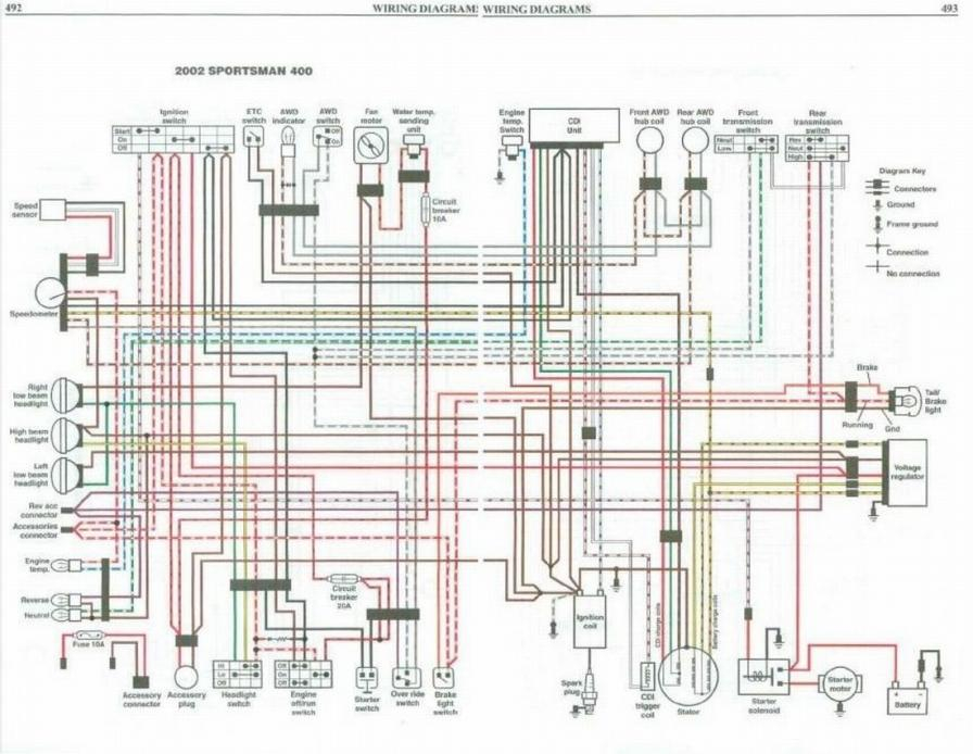
There are three switches on an ignition switch, which feed the battery’s voltage to several different locations. The first switch powers the choke. The second switch is responsible for the ON/OFF function of the ignition switch. Different manufacturers utilize their own color-coding method for different conductors which is explained in a different article. OMC utilizes this method. This connector allows the connection of a speedometer to the ignition switch.
Even though some of the ignition switch terminals could not be original, the numbering of the terminals may not be in line with the diagram. Verify the integrity of the wires first to ensure they are correctly plugged in the ignition switch. This can be done using a simple multimeter. After you’ve confirmed the integrity of the wires you can connect the connector. If you’re using an ignition switch that is supplied by the manufacturer, the wiring loom is different from the one in your car.
Before you can connect the ACC outputs to your car’s auxiliary outputs It is essential to be familiar with the fundamentals of these connections. The ACC and IGN connectors are the standard connections of the ignition switch. While the START, IGN, and ACC terminals are primary connections for the radio or stereo, the START/IGN terminals are the primary ones. The ignition switch is the one that turns the engine of your car on and off. The terminals of older cars ignition switches are identified with “ACC” as well as ST (for individual magneto wires).
Terminals for coil
Understanding the terminology that is used is the initial step to determining what type of ignition coil. In a typical ignition wiring diagram there are various terminals and connections, including two primary and two secondary. The operating voltage of every coil is different. This is why it is crucial to test the voltage at S1 (primary terminal). S1 should also undergo resistance tests to determine if it is a Type A or B coil.
The coil’s low-tension end must be connected to the chassis positively. It is also the ground for an ignition wiring diagram. The high-tension side delivers positively direct to the spark plugs. For suppression purposes, the coil’s body metal must be connected with the chassis. It is not required for electrical use. The ignition wiring diagram will also outline the connection of the positive coil’s terminals. Sometimes, a visit to an auto parts shop can identify a problem with the ignition wire.
The black-and-white-striped wire from the harness goes to the negative terminal. The white wire is the other one. It has a black trace on it and it connects to the positive terminal. The contact breaker is attached to the black wire. If you’re unsure of the connection between both, you can use an old paper clip to take them from the housing of the plug. Also, make sure to check that the terminals haven’t been bent.
Accessory terminals
The diagrams for ignition wiring show the wires used in the power supply of the vehicle. Each component is equipped with four distinct connections that are color coded. Accessories are red while the battery is yellow, the starter solenoid green. The “IGN” terminal allows you to start the car, control the wipers, and any other operation features. The diagram illustrates how you can connect ACC or ST terminals and the rest.
The terminal BAT connects the battery to the charger. The electrical system won’t start without the battery. A dead battery could cause the switch to stop turning on. It is possible to view your wiring diagram to determine where your car’s batteries are placed. The ignition switch and battery are connected via accessory terminals. The BAT Terminal is connected to the battery.
Some ignition switches come with a separate “accessory” position, in which users can manage their outputs with no ignition. Some customers prefer to make use of an additional output that is independent of the ignition. Make use of the secondary output by connecting the connector to the ACC terminal on the switch that has the same color. While this is an excellent option, there’s an crucial distinction. Most ignition switches come with the ACC position when your vehicle is in ACC mode and a START position when you are in IGN.
Gallery of 2004 Polaris Sportsman 400 Ignition Switch Wiring Diagram

Gallery of 2004 Polaris Sportsman 400 Ignition Switch Wiring Diagram


