Mg Midget Ignition Switch Wiring Diagram – First, we will examine the different types of terminals that are used on the ignition switch. The terminals are the Ignition switch as well as the Coil as well as the Accessory. Once we know the purpose of each kind of terminal, we are able to identify the various components of the ignition wiring. We will also talk about the functions as well as the Coil. We’ll then turn our attention on the accessory terminals.
Terminals for ignition switches
There are three switches in an ignition switch that provide the battery’s voltage to a variety of locations. The first switch provides the choke with power when it is pushed. The second is the switch that controls the ignition’s ON/OFF positions. Different manufacturers have their own color-coding system for different conductors that is described in a separate article. OMC employs this system. This connector allows the connection of a speedometer to the ignition switch.
Although the majority of ignition switch terminals don’t carry an original number, they might be equipped with a different number. The first step is to check the continuity of each wire to make sure they’re properly connected to the ignition switches. A cheap multimeter can assist you in this. When you are satisfied with the continuity of the wires it is time to connect the new connector. If your car has an original ignition switch supplied by the factory (or an electrical loom), the wiring loom will differ from that of your car.
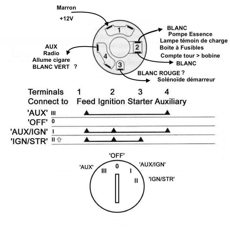
To connect the ACC outputs to the auxiliary outputs of your car, you’ll need to understand the way these two connections function. The ACC/IGN terminals function as the default connections for the ignition switch. The START/IGN connections connect to the stereo or radio. The ignition switch is responsible for turning the engine of your car to and off. The terminals on older cars ignition switches are marked by “ACC” and ST (for individual magneto wires).
Terminals for coil
The language used to decide the model and type of the ignition coil is the most important thing. In a typical ignition wiring diagram, you will see various terminals and connections, including two primary and two secondary. The coils have a specific operating voltage. The initial step to determine which one you have will involve testing the voltage of S1 the main terminal. To determine if the coil is a Type A, C, or B coil, you must also test the resistance on S1’s.
The negative end of the chassis must be connected to connect to the coil’s lower-tension end. This is what you find in the wiring diagram. The high-tension supply supplies positive directly to spark plugs. To prevent noise, the coil’s body metal must be connected with the chassis. It’s not necessary to use electricity. The wiring diagram will also illustrate the connection between the positive and negative coils. In certain instances it is possible to find a malfunctioned ignition coil is identified by scans in an auto parts store.
The black-and-white-striped wire from the harness goes to the negative terminal. The other white wire has a black color and connects to the negative terminal. The black wire is connected to the contact breaker. It is possible to remove the black wire from the plug housing using a paper clip if you are unsure about the connections. Also, make sure to check that the terminals aren’t bent.
Accessory terminals
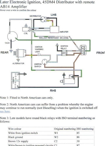
Ignition wiring diagrams show the different wires that are used to power the car’s various parts. In general there are four colors-coded terminals that are used for each component. The red color is for accessories, yellow the battery and green is the starter solenoid. The “IGN” terminal is used to start the car, operate the wipers, and other features. The diagram shows how you can connect the ACC and ST terminals to the rest of the components.
The terminal BAT is where the battery is. Without the battery the electrical system will not begin. Furthermore, the switch doesn’t turn on. The wiring diagram will tell you where to find the battery of your car. The accessory terminals in your car are connected to the battery as well as the ignition button. The BAT terminal is connected to the battery.
Some ignition switches come with an additional position. It allows users to access their outputs from a different location without the ignition. Some customers may prefer to use the auxiliary output in addition to the ignition. It is possible to use the additional input by connecting the connector to the ACC terminal. This is a useful feature, but there is an important distinction. Many ignition switches can be configured to be in an ACC position when the vehicle has moved into the ACC position. They’ll also be in START mode once the vehicle is entered the IGN position.
Gallery of Mg Midget Ignition Switch Wiring Diagram
Gallery of Mg Midget Ignition Switch Wiring Diagram


