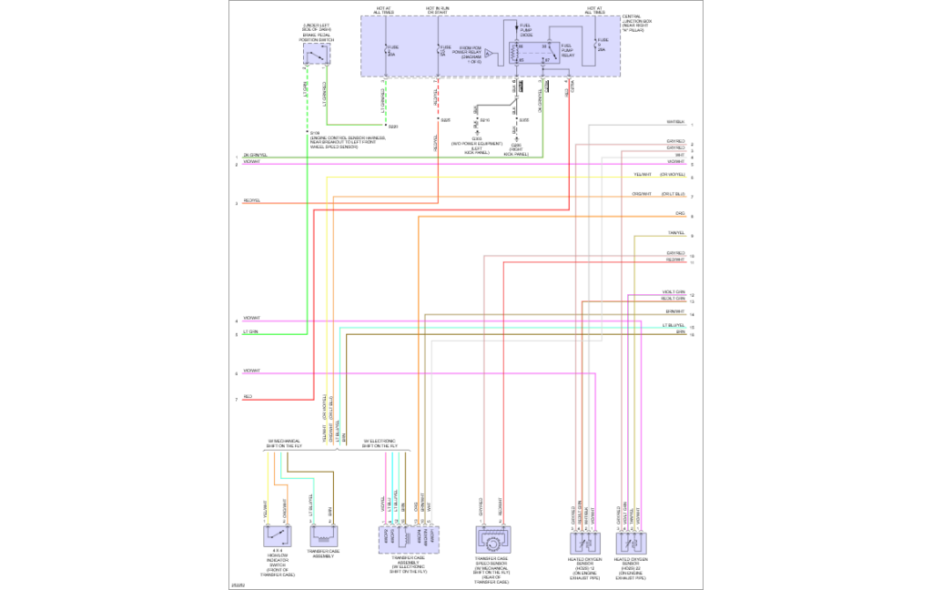
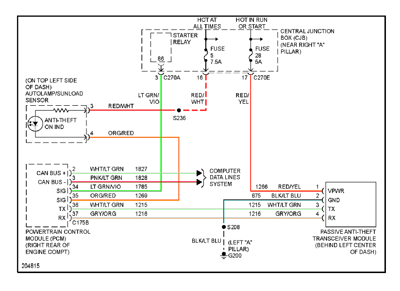
2007 Ford F150 Ignition Wiring Diagram – We’ll begin by looking at the different kinds of terminals that are found in an ignition switch. They include terminals for the Ignition switch, Coil, and Accessory. After we’ve identified the terminals that are utilized, we can begin to recognize the various parts of the 2007 Ford F150 Ignition Wiring Diagram. We will also discuss the functions of the Ignition switch and Coil. After that, we’ll turn our attention to Accessory terminals.
Terminals for ignition switches
An ignition switch has three switches. They supply the voltage of the battery to many different places. The first is utilized to power the choke by pushing it, while another switch controls the ON/OFF setting. Different manufacturers use different color-coding methods for different conductors. This will be covered in another article. OMC employs this system. Connectors can be connected to the ignition switch to include a digital Tachometer.
While the majority of the ignition switch terminals aren’t authentic, the numbering of each may not match the diagram. You should first check the electrical continuity to see if they are plugged into the correct ignition switch. This can be accomplished using a cheap multimeter. Once you are satisfied that the wires are in good continuity then you can connect the new connector. If your car has an ignition switch installed the wiring diagram will differ.
You must first understand the ways in which the ACC outputs and auxiliary outputs work in order to connect them. The ACC, IGN and START terminals are the default connections to the ignition switch. They are also the primary connections to the radio and stereo. The ignition switch switches the engine of your car ON and OFF. The terminals of older cars ignition switches are marked with “ACC” and ST (for specific magneto wires).
Terminals for coil
The terminology used to determine the type and model of the ignition coil is the first thing. A basic ignition wiring diagram will reveal a variety of connections and terminals, which include two primary terminals and two secondary. The voltage that operates on each coil differs. It is crucial to test the voltage at the S1 (primary terminal). S1 should also be tested for resistance in order to identify if it’s an A, Type B, or an A coil.
The coil’s low-tension end is to be connected to the chassis’ positive. This is exactly what you can see on the wiring diagram. The high-tension part supplies positive direct to the sparkplugs. It is essential for the purpose of suppression that the metallic body of the coil is connected to its chassis, however, it is not necessary. The diagram of the ignition wiring will also show you how to connect the positive and negative coil terminals. Sometimes, a damaged ignition coil is identified by a scan done in an auto parts shop.
The black-and-white-striped wire from the harness goes to the negative terminal. The other white wire is black and connects to the negative terminal. The contact breaker is linked to the black wire. To verify the connections between the two wires employ a paperclip to lift them out of the housing. Make sure the terminals aren’t bent.
Accessory Terminals
Diagrams of ignition wiring show the various wires utilized to power various components. There are usually four color-coded terminus for each component. The accessories are colored red while the battery is yellow the starter solenoid is green. The “IGN terminal” is used to run the wipers, as well as other operating features. The diagram shows the connection of the ACCas well as ST terminals.
The battery is connected to the terminal whose name is BAT. The battery is essential to allow the electrical system to get started. The switch won’t turn on if there is no battery there. You may refer to the wiring diagram if you’re uncertain about where the car’s batteries are located. The ignition switch and the battery are connected via accessory terminals. The BAT connector connects to your battery.
Some ignition switches come with an additional “accessory” location, which allows users can control their outputs without using the ignition. In some cases, users may want to utilize the auxiliary output separately from the ignition. You can use the secondary input by connecting the connector to the ACC terminal. This convenience feature is great, but there is one distinction. A lot of ignition switches can be programmed to have an ACC position once the car has been moved into the ACC position. They also will be in the START position when the vehicle has entered the IGN position.
Gallery of 2007 Ford F150 Ignition Wiring Diagram
Gallery of 2007 Ford F150 Ignition Wiring Diagram


