Davis Unified Ignition Wiring Diagram – Let’s begin by examining the different types and functions of the terminals in the ignition switches. These terminals are used for the Ignition button, Coil and Accessory. Once we know the terminals used, we can begin to determine the various components of the Davis Unified Ignition Wiring Diagram. Then, we will discuss the roles of the Ignition switch as well as the Coil. After that, we will concentrate on the accessory terminals.
The terminals are for ignition switches.
There are three switches on an ignition switch, which transmit the battery’s current voltage to various places. The choke is powered by the first switch. The third switch regulates the ON/OFF of the ignition switch. Different manufacturers use various color codes for the different conductors. This is described in a different article. OMC utilizes this method. The ignition switch comes with an option to connect an Tachometer.
While many ignition switch terminals could not be original, the numbers of each may not be in line with the diagram. First, check the continuity of all the wires to ensure they are correctly connected to the ignition switches. This can be done using a simple multimeter. After you’ve confirmed the integrity of the wires you can connect the connector. If your car has an original factory-supplied ignition switch (or wiring loom) the wiring loom may differ from that of the car.
Understanding how the ACC outputs are connected to the other outputs of your car is essential. The ACC and IGN connectors are the default connections of your ignition switch. Although the START, IGN, and ACC terminals are the primary connections for the radio or stereo, the START/IGN connections are the primary ones. The ignition switch operates the engine’s off/on button. The terminals of older cars ignition switches are marked with “ACC” as well as ST (for specific magneto wires).
Terminals for coil
The terminology used to determine the type and model of an ignition coil is the most important thing. The fundamental diagram of ignition wiring illustrates a variety of connections and terminals. There are two primary and secondary connections. Each coil is operating at a certain voltage. The first step to determine which type you’re using is to examine the voltage at S1 or the primary terminal. S1 should also be tested for resistance to determine if it’s a Type B, B, or A coil.
The coil’s low-tension end must be connected to the chassis’ positive. This is also the ground in the wiring diagram for ignition. The high tension side supplies positively directly to the spark plugs. The metal body of the coil needs to be connected to the chassis to suppress the effect but is not electrically required. The wiring diagram will also illustrate the connection between the positive and negative coil terminals. In some instances, you’ll find that a malfunctioned ignition coil can be diagnosed with a scan in an auto parts store.
The black-and-white-striped wire from the harness goes to the negative terminal. The other white wire is black-colored and connects to the terminal opposite. The contact breaker is linked to the black wire. It is possible to check the connections with a paperclip to take the wires out of the housing. Make sure you don’t bend the connectors.
Accessory terminals
Diagrams of ignition wiring show the various wires used to power the car’s various components. In general there are four distinct color-coded terminals for each component. The accessories are colored red, the battery is yellow, the starter solenoid green. The “IGN” terminal allows you to start the car, manage the wipers or other features that operate. The diagram shows how you can connect the ACC and ST terminals to the rest of the components.
The battery is attached to the terminal called BAT. The electrical system can’t be started without the battery. Also, the switch won’t be able to turn on without the battery. You may refer to the wiring diagram if you’re uncertain about where the car’s batteries are located. The ignition switch is connected to the car’s battery. The BAT Terminal is connected to the battery.
Certain ignition switches have an accessory setting where users can alter their outputs and manage them without needing to use the ignition. Customers may want to utilize the auxiliary output in addition to the ignition. In order for the auxiliary output be used, connect the connector in the same color as the ignition. Then connect it with the ACC end of the switch. Although this is a great option, there’s a thing you should know. The majority of ignition switches are set to have an ACC position when the vehicle is in the ACC position, whereas they’re in the START position when the car is in the IGN position.
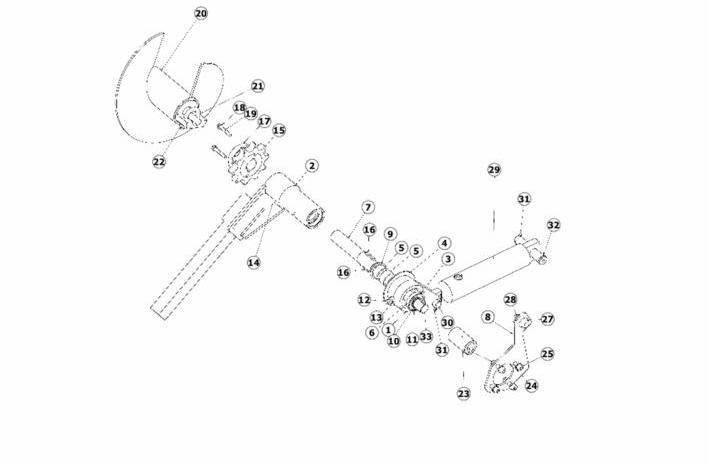
Gallery of Davis Unified Ignition Wiring Diagram
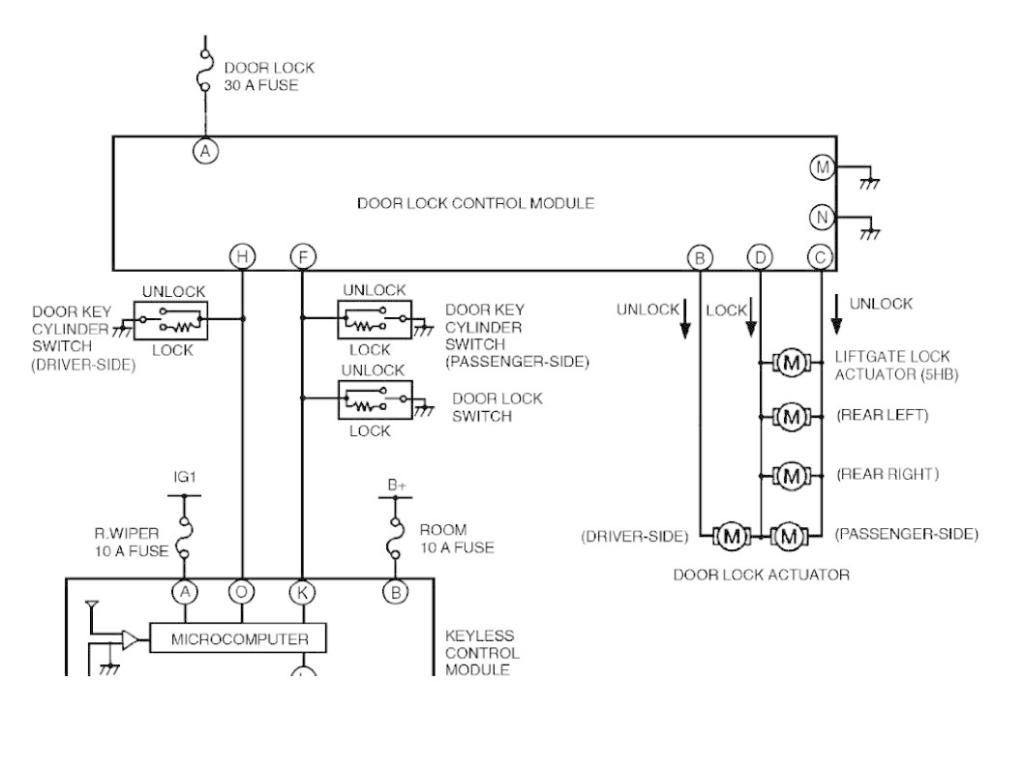
Gallery of Davis Unified Ignition Wiring Diagram


