22r Ignition Coil Wiring Diagram – Let’s begin by looking at the various types of terminals in an ignition switch. These include terminals for Coil, Ignition Switch, and Accessory. Once we’ve established the purpose of the terminals we will be able to determine the various components of the ignition wiring. We will also discuss what functions are available for the Ignition switch, as well as the Coil. Then, we will concentrate on the accessories terminals.
Terminals for ignition switches
There are three switches in the ignition switch, and they feed the battery’s voltage to several different locations. The ON/OFF state of the switch that controls the ignition is managed by the first switch, which supplies power to the choke when it’s pushed. Each manufacturer has their individual color-coding system that we’ll discuss in a subsequent article. OMC employs this system. The connector allows for the attachment of a speedometer the ignition switch.
Although the majority of ignition switch terminals are duplicated, the number may not be consistent with the diagram. Before you plug into the ignition switch ensure that you check the continuity. This can be done with a simple multimeter. When you are happy with the continuity of the wires, install the new connector. The wiring loom in an ignition system switch that is supplied by the manufacturer is distinct.
It is important to know the differences between the ACC and the auxiliary outputs. The ACC terminals and IGN terminals are the default connections to your ignition switch. The START and IGN connections are the most important connections for radio and stereo. The ignition switch is responsible for turning the car’s engine to and off. Older cars are identified by the alphabets “ACC”, “ST”, (for individual magneto cables) on their ignition switch terminals.
Terminals for coil
To figure out the type of ignition coil you need to know the step is to know the terminology. The fundamental diagram of ignition wiring depicts various connections and terminals. There are two primary and one secondary. You must determine the type of coil you have by testing the voltage at the primary terminal, called S1. Also, you should test S1 for resistance to identify if it’s an A, B, or C coil.
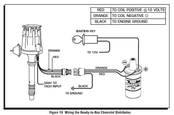
The coil with low tension must be connected to the chassis’s minus. It is also the ground in the diagram of ignition wiring. The high-tension part supplies the spark plugs with positive. The aluminum body of the coil needs to be linked to the chassis to prevent it from being smothered however it’s not electrically required. A wiring diagram can also depict the connection between positive and negative coils. In some instances you’ll discover that a malfunctioned ignition coil is identified by a scan at an auto parts store.
The black-and-white-striped wire from the harness goes to the negative terminal. The positive terminal is connected to the white wire and the trace of black. The black wire connects to the contact breaker. You can check the connections using a paperclip to take the wires out of the housing. Check that you don’t bend the connectors.
Accessory terminals
Ignition wiring diagrams depict the different wires used for powering the various components. Typically there are four colored terminals for each part. The red symbol represents accessories, yellow is for the battery and green is for the starter solenoid. The “IGN terminal allows you to start the car, control the wipers, and any other functions. The diagram illustrates how to connect ACC or ST terminals and the rest.
The terminal BAT is where the battery is. The electrical system won’t start if the battery isn’t connected. In addition the switch isn’t turned on. If you don’t know where your car’s battery is situated, you can review your wiring diagram to figure out how to locate it. The ignition switch and the battery are connected through the accessory terminals. The BAT Terminal is connected to the battery.
Some ignition switches have the “accessory” setting that permits users to control their outputs without having to use the ignition. Customers sometimes want the output of the auxiliary to be used independently from the ignition. To allow the auxiliary output to be used, plug in the connector to the same shade as the ignition. Connect it to the ACC end of the switch. Although this is a useful feature, there’s one significant difference. Most ignition switches will be in an ACC position when the vehicle is in ACC however, they’ll be in the START position when the vehicle is in IGN.
Gallery of 22r Ignition Coil Wiring Diagram
Gallery of 22r Ignition Coil Wiring Diagram


