Boat Ignition Key Wiring Diagram – Let’s first examine the different types and functions of the terminals in the ignition switches. These terminals include the Ignition switch and Coil as well as the Accessory. Once we know the terminals used then we can recognize the various parts of the Boat Ignition Key Wiring Diagram. We’ll also discuss the functions of the Ignition switch and Coil. We’ll then turn our attention to the accessory terminals.
Terminals for ignition switches
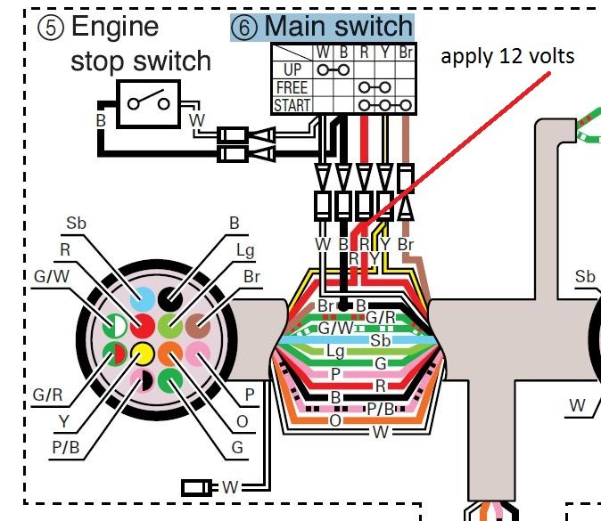
An ignition switch is composed of three switches. They are the ones that supply the battery’s power to various places. The first switch is the one that supplies the choke with power, while the second toggles the status of the ignition switch. Different manufacturers utilize their own color-coding method for the various conductors, which is explained in a different article. OMC follows this scheme. There is a connector in the ignition switch for connecting the tachometer.
While most ignition switch terminals may not be original, the numbers for each might not be consistent with the diagram. Check the integrity of the wires first to make sure they’re properly connected to the ignition switch. A cheap multimeter can assist you in this. Once you’re satisfied with the continuity, you can place the new connector. If you have an ignition switch supplied by the manufacturer the wiring loom may be different from the one used in your vehicle.
For connecting the ACC outputs to the auxiliary outputs of your vehicle, you have to understand how these two connections work. The ACC and IGN connectors are the default connections for your ignition switch. While the START, IGN, and ACC terminals are the primary connections to the radio or stereo, the START/IGN connections are the primary ones. The ignition switch controls the car’s engine. Older cars are identified by the alphabets “ACC”, “ST”, (for individual magneto cables) at the ignition switch terminals.
Terminals for Coil
The first step to determine the kind of ignition coil is to comprehend the terminology used. You’ll see a number of connections and terminals on an ignition wiring schematic which includes two primary as well as two secondary. You need to determine the type of coil you have by testing the voltage on the primary terminal, called S1. S1 should be tested for resistance in order to identify if the coil belongs to Type A, B, or C.
The negative end of the chassis should be connected to to the coil’s lower-tension end. This is what you see in the diagram of wiring. The high-tension side provides positive direct to the sparkplugs. To reduce the noise, the coil’s metal body is required to be connected to the chassis. However, it is not necessary to electrically connect. The diagram for the ignition wiring will also demonstrate the connections between the positive and negative coil’s terminals. In certain instances, a scan at your local auto parts store will be able to diagnose the malfunctioning ignition coils.
The black-and-white-striped wire from the harness goes to the negative terminal. The other white wire is black-colored and goes to the terminal opposite. The black wire is connected to the contactbreaker. If you’re unsure of the connections of the twowires, use a paper clip to remove them from the plug housing. Make sure that the connectors aren’t bent.
Accessory Terminals
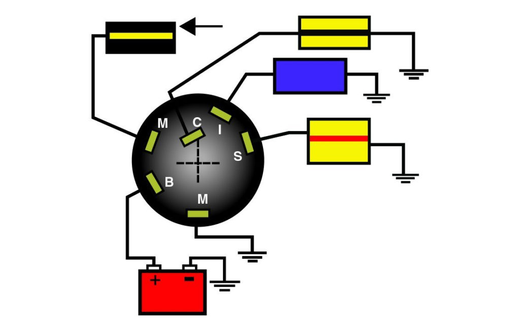
The ignition wiring diagrams show the different wires used to power the different components. There are typically four color-coded terminals that correspond to the component. The accessories are red and the battery yellow the starter solenoid green. The “IGN” terminal is used to turn on the car, control the wipers, as well as other features. This diagram shows how you can connect ACC and ST terminals to the rest of the components.
The terminal called BAT is where the battery is connected. The electrical system can’t be started without the battery. A dead battery could make the switch not turn on. You can refer to your wiring diagram if you are uncertain about where the car’s batteries are. The accessory terminals of your vehicle are connected to the battery and the ignition button. The BAT terminal is connected to the battery.
Certain ignition switches have an accessory position where users can modify their outputs as well as control them without having to turn on the ignition. In some cases, users may want to use the auxiliary input separately from the ignition. You can use the secondary output by connecting it to the ACC terminal on the switch using the same colors. While this is an excellent option, there’s an important difference. Most ignition switches are configured to be in an ACC position when the vehicle is in the ACC position, while they’re in the START position when the vehicle is in the IGN position.
Gallery of Boat Ignition Key Wiring Diagram
Gallery of Boat Ignition Key Wiring Diagram


