22r Ignition Wiring Diagram – The first step is to take a look at the different kinds of terminals for the ignition switch. These include the terminals for the Ignition switch, Coil, and Accessory. Once we have identified what these terminals do, we will be able to identify the various parts of the ignition wiring. In addition, we will discuss the roles of the Ignition switch and Coil. We will then turn our attention towards the accessories terminals.
Terminals for the ignition switch
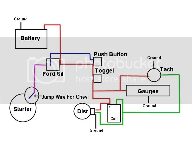
Three switches can be found on an ignition switch. Each of the three switches transmits the battery’s current to several different places. The first one is used to power the choke through pushing it. Then, the third switch is used to control the ON/OFF setting. Each manufacturer has their unique color-coding system, which we will discuss in another article. OMC follows this system. An additional connector is included inside the ignition switch for connecting the tachometer.
Even though many ignition switch terminals don’t appear in their original configuration, the numbering may not match that of the diagram. Before you plug in the ignition switch, be sure to test the continuity. A simple multimeter will assist you in this. After you’re satisfied with the continuity then you can connect the new connector. If your car has an original factory-supplied ignition switch (or wiring loom), the wiring loom will differ from that in your car.
Understanding how the ACC outputs connect to the other outputs inside your car is vital. The ACC terminals and IGN terminals serve as the default connections to the ignition switch. The START and IGN connections are the most important connections for stereo and radio. The ignition switch is responsible for turning the engine of your car on and off. The terminals of older vehicles ignition switches are identified by “ACC” as well as ST (for individual magneto wires).
Terminals for coil
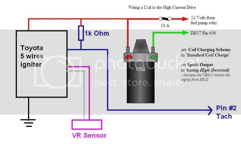
The terms used to define the kind and model of the ignition coil is the primary thing. An ignition wiring diagram will reveal a variety of terminals and connections which include two primary terminals and two secondary. Each coil comes with its own operating voltage. To determine the type of coil you’ve got the first step is to test the voltage at the S1 primary terminal. You should also test S1 for resistance in order to determine whether it is a Type A B, C, or coil.
The coil’s low-tension side must be connected to the chassis positive. This is also the ground for an ignition wiring diagram. The high-tension supply delivers the spark plugs with positive electricity directly. For suppression purposes, the coil’s body metal must be connected with the chassis. It is not required to use electricity. A wiring diagram can show the connection between the positive and negative coil terminals. In certain instances it is possible to find a malfunctioned ignition coil is easily identified with a scan at an auto parts store.
The black-and-white-striped wire from the harness goes to the negative terminal. The terminal that is negative is served by the black trace connected to the white wire. The black wire goes to the contact breaker. You can take the black wire from the plug housing by using a paperclip if you are unsure about the connection. Also, make sure to verify that the connections haven’t been bent.
Accessory Terminals
The ignition wiring diagrams illustrate the different wires that are used to power various components of the car. There are generally four colors of terminals connected to each part. Red is used to indicate accessories, yellow to the battery, and green is the starter solenoid. The “IGN terminal is used for starting the car, operating the wipers, and for other functions. This diagram shows how you can connect ACC and ST terminals to the rest of the components.
The terminal BAT connects the battery to the charger. The electrical system is not able to begin without the battery. A dead battery can make the switch not come on. To locate your car’s battery examine the wiring diagram. The accessory terminals of your car are connected to the battery and the ignition switch. The BAT terminal is connected to the battery.
Certain ignition switches have an additional position in which users can modify their outputs and control them without having to turn on the ignition. Some customers want the auxiliary output to be used independently from the ignition. You can utilize the secondary input by connecting the connector to the ACC terminal. This is an excellent option, but there’s an important distinction. Most ignition switches come with the ACC position when the car is in the ACC mode, and a START position when you are in IGN.
Gallery of 22r Ignition Wiring Diagram
Gallery of 22r Ignition Wiring Diagram


