3 Terminal Ignition Switch Wiring Diagram – Let’s first examine the different kinds and functions of terminals that are found in the ignition switches. These terminals are for the Ignition button, Coil and Accessory. Once we’ve established the purpose of these terminals, we can determine the various components of the ignition wiring. We’ll also be discussing the function of the Ignition switch, as well as the Coil. Then we’ll proceed to the Accessory Terminals.
Terminals for ignition switches
An ignition switch is composed of three different switches. They are the ones that supply the battery’s power to several destinations. The first switch supplies the choke with power when it is pushed. The second is the switch that controls the ignition’s ON/OFF positions. Different manufacturers have different colors-coding systems to match the conductors. OMC uses this system. The connector permits the attachment of a speedometer to the ignition switch.
Even though most ignition switch terminals don’t have an original number, they may have a different one. Check the integrity of the wires first to ensure that they’re connected correctly to the ignition switch. A multimeter is a great tool to test the continuity. Once you’ve verified the integrity of the wires you can then connect the connector. If your car has an original ignition switch supplied by the factory (or an electrical loom) The wiring loom might differ from that in your car.
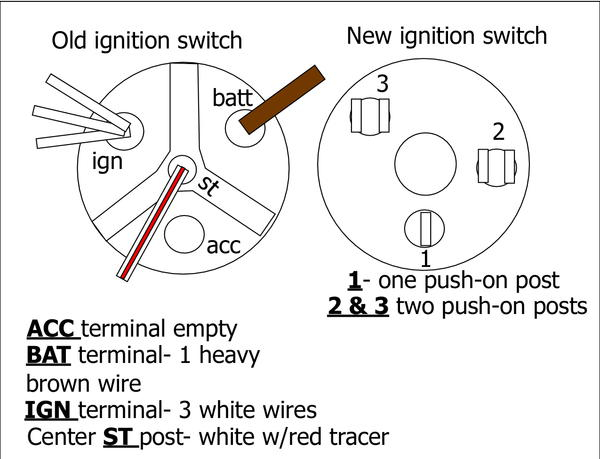
It is important to understand how the ACC outputs and the auxiliary outputs function in order to join them. The ACC terminals as well as the IGN terminals are the standard connections for the ignition switch. The START and IGN connections are the most important connections for stereo and radio. The ignition switch turns the car’s engine on and off. In older vehicles the terminals of the ignition switch are identified with the initials “ACC” as well as “ST” (for individual magnetic wires).
Terminals for Coil
The first step in determining the kind of ignition coil is to understand the terminology used. An ignition wiring diagram will reveal a variety of terminals and connections, which include two primary terminals and two secondaries. The coils have a specific operating voltage. The initial method of determining what type you have will involve testing the voltage at S1, the main terminal. To determine whether it’s an A, C, or B coil you must also test S1’s resistance.
The chassis’ negative needs to be connected to the low-tension side. This is the ground on the ignition wiring diagram. The high-tension side provides positive direct to the sparkplugs. The coil’s aluminum body needs to be connected to the chassis for suppression but isn’t required. The diagram of the ignition wiring will also reveal the connection of the positive and negative coil terminals. Sometimes, an inspection at an auto part store can diagnose a malfunctioning ignition wire.
The black-and-white-striped wire from the harness goes to the negative terminal. The terminal for the negative is served by the trace in black that’s connected to the white wire. The contact breaker is linked to the black wire. To test the connections between the two wires use a paperclip and remove them out of the housing. Be sure the terminals do not bend.
Accessory Terminals
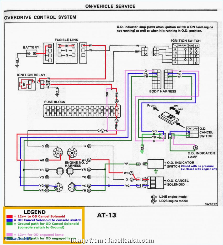
Ignition wiring diagrams depict the different wires used to power various components. There are generally four terminals with color codes that are connected to each component. The red color is used for accessories, yellow is for the battery, and green is the starter solenoid. The “IGN terminal is used for starting the car, operating the wipers, and for other functions. This diagram shows how to connect ACC and ST terminals with the rest of the components.
The battery is connected to the terminal called BAT. Without the battery the electrical system will not start. Additionally, the switch will not start without the battery. You may refer to the wiring diagram if you are unsure where your car’s batteries are. The ignition switch as well as the battery are connected by the accessory terminals. The BAT Terminal is connected to the Battery.
Some ignition switches offer an additional “accessory position” that allows users to adjust their outputs independently of the ignition. Customers sometimes want the auxiliary output to be used independently from the ignition. The auxiliary output could be used to connect the connector in the same colors as your ignition, and then attaching it to the ACC terminal of the switch. While this is a convenient feature, there’s one important difference. Most ignition switches come with an ACC position when the car is in the ACC mode and a START position when you are in IGN.
Gallery of 3 Terminal Ignition Switch Wiring Diagram
Gallery of 3 Terminal Ignition Switch Wiring Diagram


