Clark Forklift Ignition Switch Wiring Diagram – The first step is to look at the various types of terminals that are used on the ignition switch. They are the terminals used that are used for Coil, Ignition Switch, and Accessory. Once we know the purpose of each terminal, it is possible to identify the various components of the ignition wiring. In addition, we will discuss the different functions of the Ignition Switch and the Coil. We will then turn our attention towards the accessories terminals.
Terminals for ignition switch
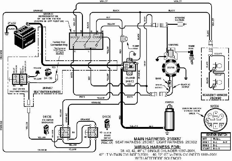
An ignition switch is made up of three switches. These are responsible for supplying the battery’s power to several places. The first switch is used to power the choke by pushing it. Then, the second is for the ON/OFF setting. Different manufacturers have different color-coding systems to identify different conductors. This will be covered in another article. OMC utilizes this method. A connector is also included in the ignition switch to allow connecting a to a tachometer.
While the majority of ignition switch terminals don’t come in original form The numbering might not be in line with the diagram. Check the electrical continuity first to ensure that they’re properly connected to the ignition switch. This can be accomplished using a cheap multimeter. After you’re sure that all wires are in good continuity and you are able to connect the new connector. If your vehicle has an original factory-supplied ignition switch (or a wiring loom) The wiring loom will differ from that in your vehicle.
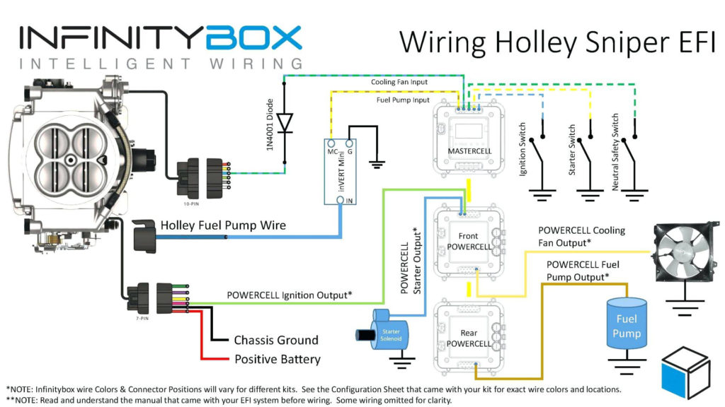
For connecting the ACC outputs to the auxiliary outputs on your vehicle, you have to first understand how these two connections work. The ACC and IGN connectors are the default connections for the ignition switch. While the START, IGN, and ACC terminals are the primary connections for radios or stereo, the START/IGN connections are the most important ones. The ignition switch acts as the engine’s on/off button. The terminals for the ignition switch on older cars are identified with the initials “ACC” and “ST” (for each magneto wires).
Terminals for coil
Understanding the terms that is used is the first step in determining what kind of ignition coil you need. You’ll see a number of connections and terminals within an ignition wiring schematic that include two primary as well as two secondary. It is essential to identify the type of coil you own by examining the voltage at the primary terminal, S1. You should also test S1 for resistance in order to determine whether it is an A B, C, or coil.
The coil’s low-tension component must be connected with the chassis positively. This is the ground in the diagram of the ignition wiring. The high-tension side provides positive direct to the sparkplugs. For suppression purposes, the coil’s body metal must be connected with the chassis. This is not necessary for electrical use. The wiring diagram of the ignition will demonstrate how to connect the terminals of either the negative or positive coils. You may find an issue with your ignition coil which can be identified by scanning it in an auto parts retailer.
The black-and-white-striped wire from the harness goes to the negative terminal. The other white wire has a black color and goes to the negative terminal. The black wire connects to the contact breaker. You can take the black wire from the plug housing by using a paperclip in case you are uncertain about the connection. Be sure to ensure that the terminals haven’t been bent.
Accessory terminals
Diagrams of ignition wiring show the different wires used to power different components. There are generally four colors-coded terminus of each part. Red is used to indicate accessories, yellow to the battery, and green for the starter solenoid. The “IGN” terminal can be used to turn on the car, control the wipers, and other functions. The diagram illustrates the connection between the ACC- and ST terminals.
The terminal known as BAT is where the battery is connected. The battery is necessary for the electrical system to get started. The switch will not turn on if there is no battery present. A wiring diagram can tell the location of the battery of your car. The accessory terminals on your car are connected to the battery and the ignition switch. The BAT connector connects to your battery.
Some ignition switches have the “accessory” setting that permits users to regulate their outputs without needing to utilize the ignition. Sometimes, customers want to use an auxiliary output independent of the ignition. To use the auxiliary output, wire the connector in the same colors as the ignition, connecting it to the ACC terminal on the switch. While this is an excellent feature, there’s one crucial distinction. Most ignition switches are set to operate in the ACC position when the car is in the ACC position, while they’re set to the START position when the car is in the IGN position.
Gallery of Clark Forklift Ignition Switch Wiring Diagram
Gallery of Clark Forklift Ignition Switch Wiring Diagram


