350z Ignition Wiring Diagram – We will first take a look at the various kinds of terminals that are found on the ignition switch. These include terminals for Coil, Ignition Switch, and Accessory. Once we know the purpose of each terminal, we are able to identify the parts of the ignition wiring. We will also discuss the functions of the Ignition switch and Coil. We will then focus on the accessories terminals.
Terminals for the ignition switch
There are three separate switches in the ignition switch, and they provide the battery’s voltage to various locations. The first switch supplies the choke with power when it is pushed. The second is the ignition switch’s ON/OFF position. Different manufacturers use their own color-coding systems for the various conductors, that is described in a separate article. OMC uses this method. A tachometer adapter is installed on the ignition switch to allow for the addition of a Tachometer.
Even though most ignition switch terminals don’t have an initial number, they could have a different number. First, check the continuity of all wires to make sure they’re properly plugged into the ignition switches. You can do this with a simple multimeter. Once you are satisfied with the continuity of the wires connect the new connector. The wiring loom used for an ignition switch that’s supplied by the factory will be different from the one in your vehicle.
It is important to know the differences between the ACC and the auxiliary outputs. The ACC terminals as well as the IGN terminals are the standard connections for your ignition switch. The START and IGN connections are the most important connections for radio and stereo. The ignition switch is the one that turns the engine of your car to and off. The terminals of the ignition switch on older cars are labeled with the letters “ACC” and “ST” (for individual magneto wires).
Terminals for coil
To determine the type of ignition coil you need to know the step is to know the terminology. An ignition wiring diagram will display a range of terminals and connections which include two primary terminals and two secondary. You need to determine the type of coil that you own by examining the voltage on the primary terminal S1. S1 should also be checked for resistance in order to identify if it’s an A, Type B or A coil.
The low-tension end of the coil needs to be connected to the chassis”negative. This is also the ground in the diagram of ignition wiring. The high-tension part supplies the spark plugs with positive. The coil’s aluminum body needs to be linked to the chassis for suppression but isn’t required. The diagram for the ignition wiring will also show you the connections between the negative and positive coil terminals. In some cases you’ll discover that an ignition coil that is malfunctioning can be diagnosed with scans at an auto parts shop.
The black-and-white-striped wire from the harness goes to the negative terminal. The white wire has a black color and connects to the terminal opposite. The contact breaker is attached to the black wire. If you’re unsure of the connection between the two, try using an old paper clip to take them from the plug housing. Make sure you don’t bend the connectors.
Accessory terminals
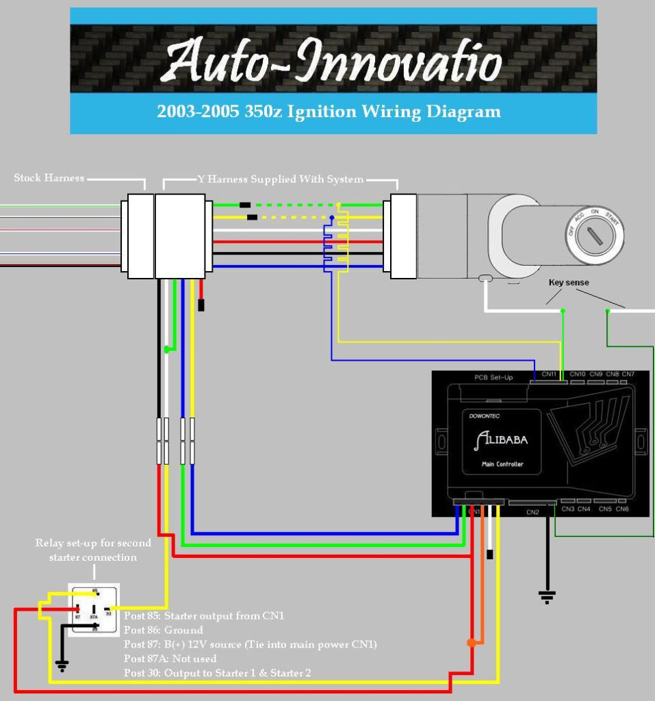
The wiring diagrams for the ignition show the various wires that provide power to the various parts of the vehicle. There are generally four colored terminals for each component. The red color is used for accessories, yellow is for the battery, while green is the starter solenoid. The “IGN terminal is used to start the vehicle, controlling the wipers and other functions. The below diagram shows how to connect both the ACC terminal as well as the ST terminals to various components.
The terminal BAT connects the battery to the charger. The electrical system cannot start without the battery. A dead battery can cause the switch to not turn on. A wiring diagram can tell the location of the battery in your car. The ignition switch as well as the battery are connected by the accessory terminals. The BAT terminal is connected to the battery.
Some ignition switches come with an additional position. This allows users to access their outputs from a different location without the ignition. Sometimes, customers wish to make use of an auxiliary output that is separate from the ignition. In order for the auxiliary output be used, wire the connector to the same color as the ignition. Then connect it with the ACC end of the switch. This is an excellent feature, however there’s an important difference. The majority of ignition switches have an ACC position if the car is in the ACC, but they will be in the START position when the vehicle is IGN.
Gallery of 350z Ignition Wiring Diagram
Gallery of 350z Ignition Wiring Diagram


