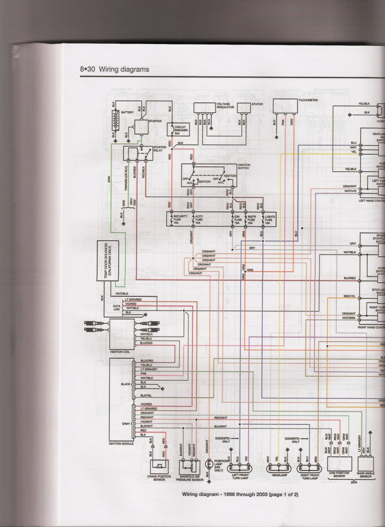
Dyna 2000 Ignition Wiring Diagram Suzuki – We will first look at the various types and functions of the terminals on the ignition switches. They are the terminals used that are used for Coil, Ignition Switch, and Accessory. After we’ve identified what these terminals are then we can determine the various components in the ignition wiring. Then, we will discuss the functions and the Coil. We will then concentrate on the accessory terminals.
Ignition switch terminals
An ignition switch is made up of three different switches. These are responsible for feeding the battery’s power to various places. The first one is utilized to turn on the choke by pushing it, while another switch controls the ON/OFF setting. Different manufacturers have different color-coding schemes for different conductors. We will cover this in a separate article. OMC utilizes this method. Connectors can be connected to the ignition switch in order to connect a digital Tachometer.
While most ignition switch terminals can be duplicated, the number may not be consistent with the diagram. To ensure that the wires are correctly connected to the ignition switch, you must verify their continuity. A multimeter is a great tool to check the continuity. When you’re happy with the continuity it’s time to connect the new connector. If you’re using an ignition switch that is supplied by the manufacturer the wiring loom will be distinct from the one that is you have in your car.
Before you can connect the ACC outputs to the auxiliary outputs of your car, it is important to be familiar with the fundamentals of these connections. The ACC/IGN connections function as the default connections on the ignition switch. The START/IGN terminals connect to the radio or stereo. The ignition switch acts as the engine’s switch to turn off or on. Older vehicles are identified with the alphabets “ACC”, “ST”, (for individual magneto cables) at the ignition switch’s terminals.
Terminals for coil
Understanding the terminology is the initial step in knowing what type of ignition coil you’ve got. You will see several connections and terminals on a basic ignition wiring schematic which includes two primary as well as two secondary. Each coil comes with its own operating voltage. To determine the type of coil you’ve got first, you need to check the voltage at S1, which is the primary terminal. S1 should also be checked for resistance in order to identify if the coil is a Type B, B, or an A coil.
The low-tension end of the coil must be connected to the chassis’ negative. This is the wiring diagram you will find in the wiring diagram. The high-tension side supplies the spark plugs with positive. It is required for suppression purposes that the coil’s metallic body be connected to its chassis, but not essential. A wiring diagram can also depict the connection between positive and negative coils. There could be an issue with the ignition coil which can be identified by scanning it at the auto parts shop.
The black-and-white-striped wire from the harness goes to the negative terminal. The positive terminal also receives the second white wire, which has a black trace. The black wire is connected to the contact breaker. To confirm the connection, employ a paperclip, or a pencil to lift them out of the housing for the plug. Also, make sure that the connections are not bent.
Accessory terminals
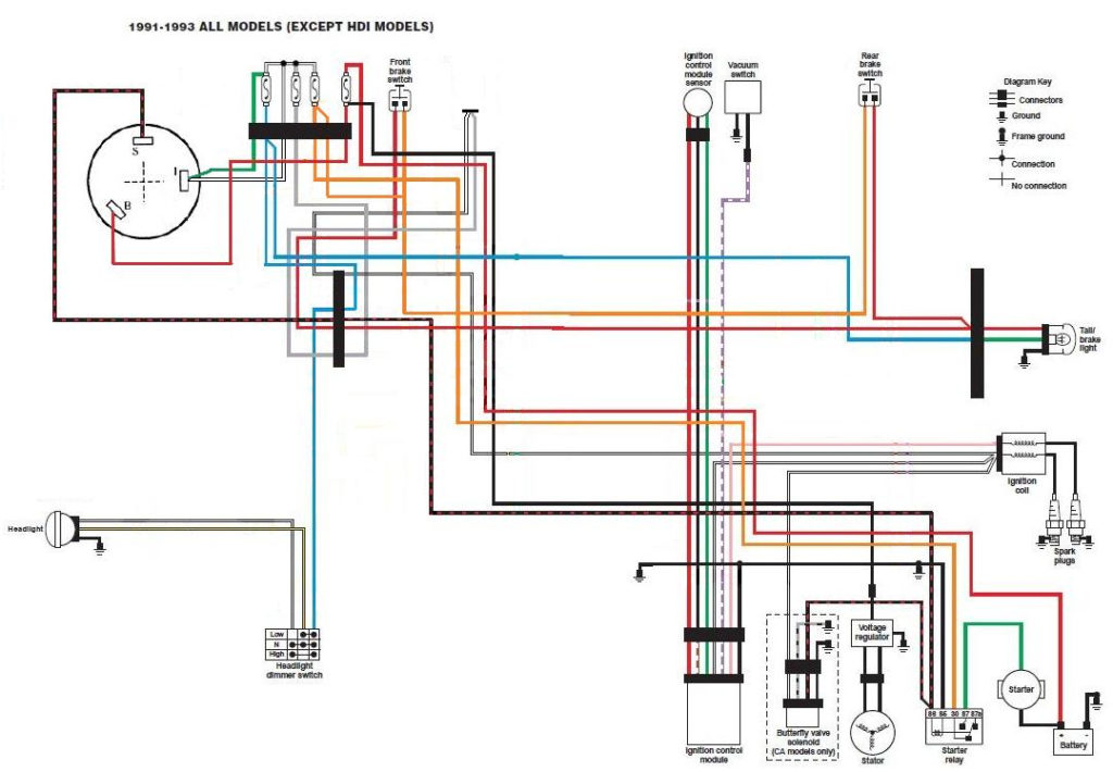
The ignition wiring diagrams illustrate the various wires utilized to power the vehicle’s various parts. Typically there are four colored terminals for each part. Red is used for accessories, yellow is for the battery, while green is for the solenoid for starters. The “IGN” terminal allows you to start the car, manage the wipers or other functions. The diagram shows how you can connect the ACC and ST terminals to the other components.
The terminal BAT holds the battery. The electrical system can’t be started without the battery. Additionally the switch isn’t turned on. If you’re not sure of the location of your car’s battery situated, you can review the wiring diagram of your car to determine the best way to find it. The accessory terminals of your car connect to the battery as well as the ignition switch. The BAT terminal connects to the battery.
Some ignition switches offer the option of an “accessory position” that allows users to adjust their outputs independently of the ignition. Sometimes, customers wish to make use of the auxiliary output separately from the ignition. To allow the auxiliary output to be used, connect the connector with the same color as that of the ignition. Connect it to the ACC end of the switch. While this is a convenient feature, there’s one crucial distinction. Many ignition switches have the ACC position when your vehicle is in ACC mode and a START mode when it is in IGN.
Gallery of Dyna 2000 Ignition Wiring Diagram Suzuki
Gallery of Dyna 2000 Ignition Wiring Diagram Suzuki


