5 Pin Ignition Switch Wiring Diagram – Let’s begin by examining the different types and functions of the terminals found in the ignition switches. These are the terminals used that are used for Coil, Ignition Switch, and Accessory. After we’ve identified the terminals that are utilized and which ones are not, we can identify the different components of the 5 Pin Ignition Switch Wiring Diagram. We will also cover the different functions of the Ignition Switch and the Coil. After that, we will concentrate on the accessories terminals.
Terminals for ignition switches
There are three separate switches on an ignition switch, which provide the battery’s voltage to several different locations. The first is utilized to drive the choke by pushing it, while the second is for the ON/OFF position. Each manufacturer has its own color-coding system, which we’ll go over in a separate article. OMC uses this method. Connectors can be connected to the ignition switch to connect an electronic tachometer.
While most ignition switch terminals are not original, the numbering for each may not match the diagram. Before you plug into the ignition switch, be sure to test the continuity. This can be accomplished with a multimeter that is inexpensive. When you are satisfied with the continuity of the wires you can install the new connector. The wiring loom in an ignition system switch that is supplied by the manufacturer is distinct.
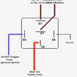
In order to connect the ACC outputs to the auxiliary outputs on your car, you’ll need to first understand the way these two connections function. The ACC terminals and IGN terminals serve as the default connections to your ignition switch. The START and IGN connections are the primary connections for radio and stereo. The ignition switch regulates the engine in your car. On older cars the ignition switch’s terminals are marked with the alphabets “ACC”, and “ST” (for the individual magnetic wires).
Coil terminals
The language used to decide the model and type of an ignition coil is the most important thing. A basic diagram of the wiring will provide you with a range of terminals and connections. The operating voltage of every coil is different. Therefore, it is important to first test the voltage at S1 (primary terminal). You should also examine S1 for resistance to determine whether it is an A, B, or C coil.
The low-tension side of the coil needs to be connected to the chassis’ negative. This is what you see on the wiring diagram. The high-tension supply provides positively directly to spark plugs. For suppression purposes, the coil’s metal body must be connected to the chassis. It is not necessary to connect the coil electrically. The wiring diagram for the ignition will explain how to connect the terminals of the positive or negative coils. Sometimes, a visit to an auto parts shop can identify a problem with the ignition wire.
The black-and-white-striped wire from the harness goes to the negative terminal. The terminal that is negative is served by the black trace that’s attached to the white wire. The black wire connects with the contact breaker. If you’re not sure about the connection between both, you can use the clip of a paperclip to remove them from the housing of the plug. Check that the terminals aren’t bent.
Accessory terminals

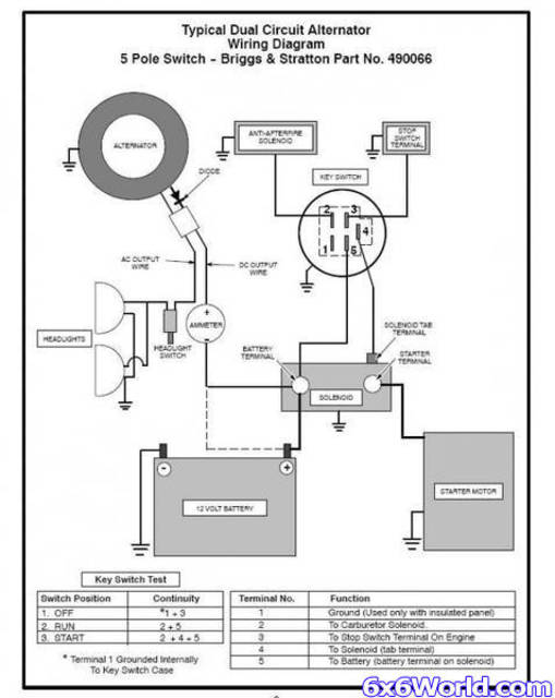
Diagrams of ignition wiring depict the wires used to power various parts of the car. There are typically four colors of terminals connected to each part. The red symbol represents accessories, yellow for the battery, and green for the starter solenoid. The “IGN” terminal allows you to start the car, control the wipers or other operation features. The diagram shows how to connect ACC or ST terminals and the rest.
The terminal BAT is where the battery is. The electrical system won’t start without the battery. A dead battery could cause the switch to stop turning on. To locate your car’s battery, check your wiring diagram. The ignition switch as well as the battery are connected through the accessory terminals. The BAT terminal connects to the battery.
Certain ignition switches have an additional position in which users can modify their outputs and manage them without the need to use the ignition. Sometimes, customers would like the output of the auxiliary to be used independently from the ignition. To allow the auxiliary output to be used, connect the connector in the same color as the ignition. Then , connect it to the ACC end of the switch. This is an excellent option, but there’s an important distinction. The majority of ignition switches are designed to have an ACC status when the car’s at either the ACC or START position.
Gallery of 5 Pin Ignition Switch Wiring Diagram
Gallery of 5 Pin Ignition Switch Wiring Diagram


