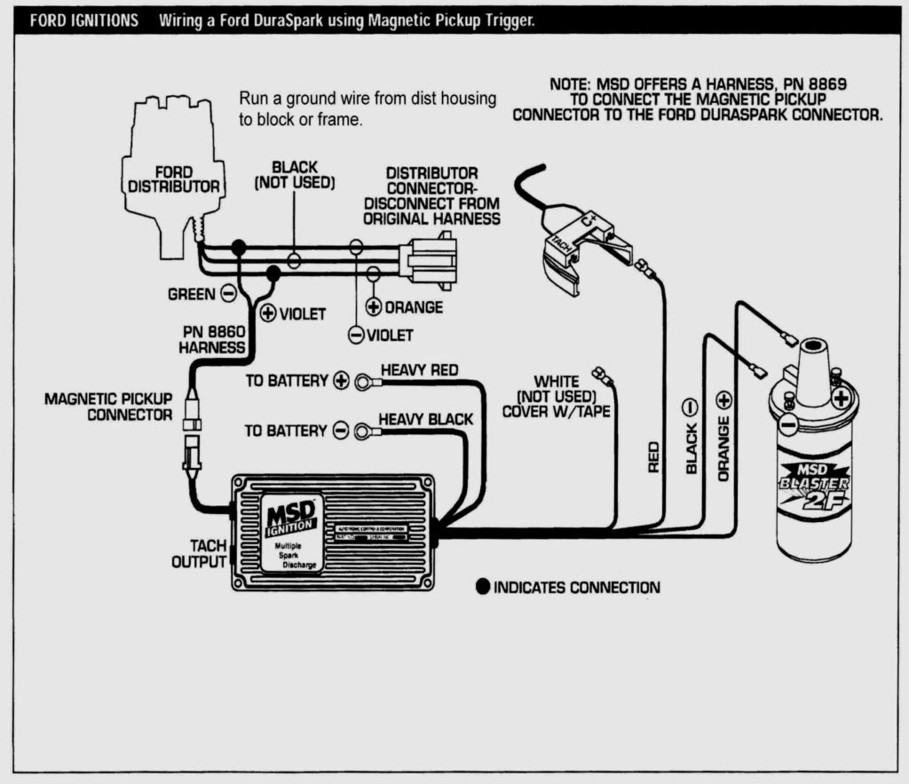
Ford Electronic Ignition Wiring Diagram – We’ll begin by looking at different types of terminals on an ignition switch. These terminals are used for the Ignition button, Coil and Accessory. When we have a clear understanding of the purpose of each kind of terminal, it is possible to determine the components of the ignition wiring. We will also talk about the functions and the Coil. Next, we’ll discuss the functions of the Ignition switch and Coil.
The terminals are for ignition switches.
The ignition switch consists of three switches. These are responsible for supplying the battery’s power to several locations. The first switch provides power to the choke, and the third switch toggles the ON/OFF status of the ignition switch. Each manufacturer has its individual color-coding system that we’ll go over in a separate article. OMC follows the same system. This connector allows the attachment of a speedometer to the ignition switch.
While the majority of ignition switch terminals don’t have an original number, they might be equipped with a different number. Check the continuity of the wires to see if they are plugged into the ignition switch in the correct way. A simple multimeter will assist you in this. Once you’ve verified the continuity of the wires you can then connect the connector. The wiring loom used for an ignition switch that’s supplied by the manufacturer will differ from the one that you have in your vehicle.
First, understand the differences between ACC and secondary outputs. The ACC, IGN and START terminals are the primary connection to the ignition switch. They also serve as the primary connections to the radio and stereo. The ignition switch is the one that turns the car’s engine on and off. Older vehicles are identified with the alphabets “ACC”, “ST”, (for individual magneto cables) on their ignition switch’s terminals.
Terminals for coil
To identify the kind of ignition coil, the initial step is to understand the definition of. In a typical ignition wiring diagram there are a number of different terminals and connections, including two primary and two secondary. You need to determine the kind of coil you are using by testing the voltage on the primary terminal S1. S1 should also be tested for resistance in order to identify if the coil is a Type B, B, or an A coil.
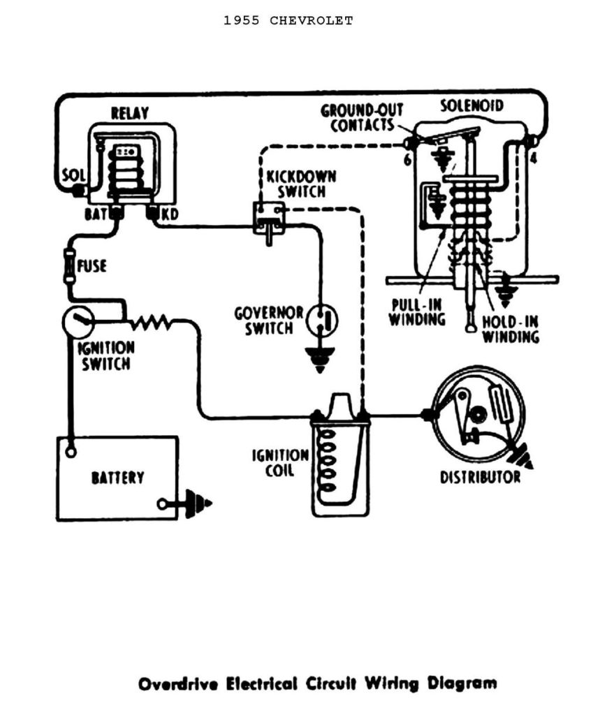
The coil with low tension must be connected at the chassis’s plus. This is what’s called the ground in the wiring diagram for ignition. The high-tension side delivers positively direct to the spark plugs. It is required for the purpose of suppression that the body of the coil’s metal be connected to its chassis, however, it is not necessary. The wiring diagram for the ignition will explain how to connect the terminals of either the positive and negative coils. Sometimes, an inspection at an auto part store can diagnose a malfunctioning ignition wire.
The black-and-white-striped wire from the harness goes to the negative terminal. The terminal that is negative is served by the trace in black that’s connected to the white wire. The contact breaker is connected to the black wire. To check the connections between the two wires, use a paperclip and lift them from the housing. You should also check to see that the terminals are not bent.
Accessory Terminals
Ignition wiring diagrams depict the different wires used for powering the different components. There are generally four color-coded terminals that correspond to the component. The red color represents accessories, yellow represents the battery, and green for the solenoid for starters. The “IGN” terminal is used to turn on the car , and also to operate the wipers and other operating functions. The diagram shows how to connect ACC or ST terminals and the rest.
The terminal known as BAT is the place where the battery is. Without the battery the electrical system will not start. The switch won’t turn on if there is no battery present. The wiring diagram will inform you the location of the battery in your car. The accessory terminals of your car are connected to the ignition switch and the battery. The BAT connector is connected to your battery.
Some ignition switches offer the option of an “accessory position” which allows users to alter their outputs without the ignition. Some customers might want to use the auxiliary input independently of the ignition. You can utilize the auxiliary input by connecting it to the ACC terminal. This is a great feature, but there is an important difference. Most ignition switches will have an ACC position when the vehicle is in the ACC however, they will be in the START position if the car is in IGN.
Gallery of Ford Electronic Ignition Wiring Diagram
Gallery of Ford Electronic Ignition Wiring Diagram


