5 Post Ignition Switch Wiring Diagram – In the beginning, we’ll take a look at the various kinds of terminals that are found on the ignition switch. These are terminals for the Ignition, Coil, or Accessory. When we have a clear understanding of the purpose of each type of terminal, we can then identify the various components of the ignition wiring. In addition, we will discuss the roles of the Ignition switch and Coil. Following that, we will proceed to the Accessory Terminals.
The ignition switch’s terminals
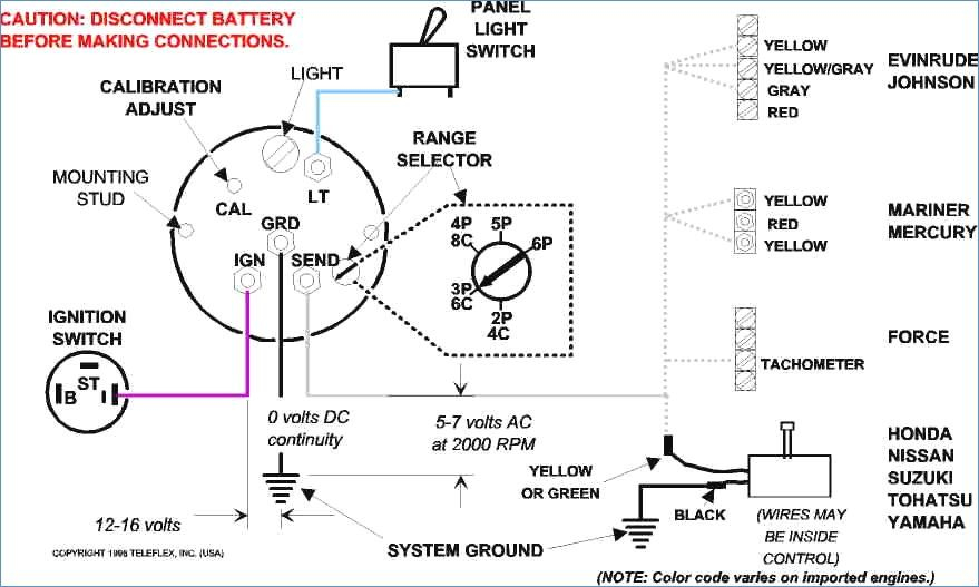
There are three separate switches in an ignition switch that feed the battery’s voltage to a variety of places. The first switch is used to turn on the choke through pushing it, and the third switch is used to control the ON/OFF position. Different manufacturers utilize their own color-coding method for different conductors which is documented in another article. OMC uses this method. The adapter is attached to the ignition switch to allow the addition of the tonometer.
Although some ignition switch terminals do not appear in their original configuration, the numbering may not match that of the diagram. You should first check the continuity of the wires to see if they are plugged into the ignition switch correctly. This can be done with a multimeter that is inexpensive. After you’re happy with the continuity of your wires, you’ll be able to connect the new connector. If your car is equipped with an original ignition switch supplied by the factory (or wiring loom) the wiring loom may differ from that in your vehicle.
It is important to understand the ways in which the ACC outputs and the auxiliary outputs function in order to join them. The ACC/IGN terminals function as the default connection on the ignition switch. The START/IGN terminals connect to the radio or stereo. The ignition switch is the one that turns the engine of your car to and off. The terminals of older vehicles ignition switches are marked by “ACC” and ST (for specific magneto wires).
Terminals for Coil
The first step to determine the type of ignition coil is to comprehend the terms employed. In a simple diagram of the wiring for ignition there are various connections and terminals, such as two primary and two secondary. You must determine the kind of coil you have by testing the voltage on the primary terminal, called S1. S1 should also be checked for resistance to determine if the coil is an A, Type B, or an A coil.
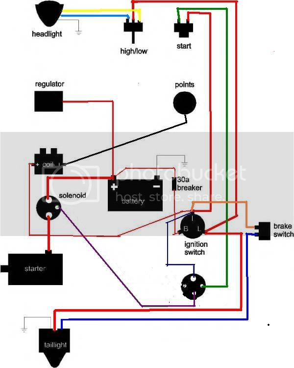
The coil’s low-tension side must be connected with the chassis positive. This is what you see in the diagram of wiring. The high-tension supply supplies the spark plugs with positive electricity directly. To prevent noise, the coil’s metal body must be connected to chassis. However, it is not required to connect electrically. A wiring diagram can show the connection between the positive and negative coil terminals. Sometimes, a visit to an auto part store can diagnose a malfunctioning ignition wire.
The black-and-white-striped wire from the harness goes to the negative terminal. The white wire also is black with a trace on it and it goes to the positive terminal. The black wire connects to the contact breaker. To test the connections between the two wires, use a paperclip to lift them from the housing. You should also check to see that the terminals are not bent.
Accessory terminals
The diagrams for ignition wiring show the wires used to power the vehicle’s electrical supply. There are generally four color-coded terminals to each component. For accessories, red is for starter solenoid, blue for battery and blue for accessory. The “IGN terminal is used for starting the car, controlling the wipers, and for other functions. The diagram shows how to connect the ACC and ST terminals to the other components.
The terminal BAT connects the battery to the charger. The electrical system will not start without the battery. A dead battery could cause the switch to not turn on. To find your car’s battery, check your wiring diagram. The accessory terminals in your vehicle connect to the battery as well as the ignition switch. The BAT connector is connected to the battery.
Some ignition switches come with an accessory position. It allows users to access their outputs from another location without the ignition. In some cases, users may want to utilize the auxiliary output separately from the ignition. The auxiliary output could be utilized to connect the connector in the same colors as your ignition and attaching it to the ACC terminal of the switch. This option is useful however, it does have one significant difference. Many ignition switches can be configured to be in an ACC position when the vehicle has moved into the ACC position. They will also be in the START mode once the vehicle is moved into the IGN position.
Gallery of 5 Post Ignition Switch Wiring Diagram
Gallery of 5 Post Ignition Switch Wiring Diagram


