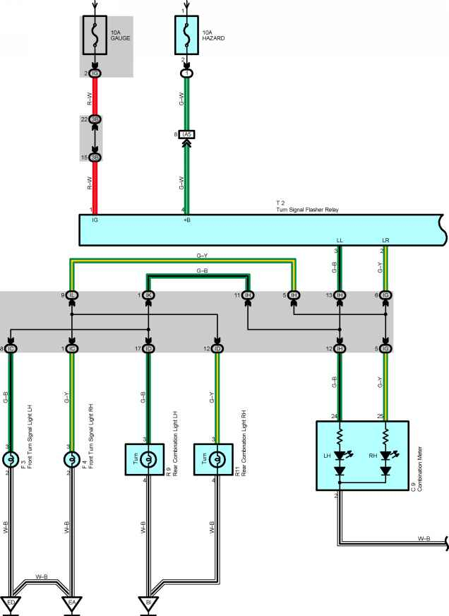
1996 Toyota Corolla Ignition Wiring Diagram – First, we will examine the various types of terminals in the ignition switch. These are the terminals that connect the Ignition, Coil, or Accessory. After we’ve identified what these terminals are then we can determine the various components in the ignition wiring. We’ll also go over the functions for the Ignition switch as well as the Coil. The next step is to focus to the accessory terminals.
Terminals for ignition switch
An ignition switch is made up of three switches. These are the ones that supply the battery’s power to several destinations. The first switch is the one that supplies power to the choke and the third switch toggles the on/off status of the ignition switch. Each manufacturer has their unique color-coding system, which we’ll discuss in a subsequent article. OMC utilizes this system. An adapter is included on the ignition switch to allow for the addition of the Tachometer.
Even though most ignition switch terminals don’t have an original number, they might be equipped with a different number. Verify the integrity of the wires first to ensure they’re properly connected to the ignition switch. A multimeter is a great tool to check the continuity. Once you’ve verified the integrity of the wires you are able to install the connector. If your vehicle is equipped with an ignition switch that is installed, the wiring diagram will differ.
Knowing how the ACC outputs are connected to the other outputs in your vehicle is crucial. The ACC, IGN and START terminals are the primary connections to the ignition switch. They are also the primary connections to the radio and stereo. The ignition switch is accountable for turning the car’s engine on and off. Older cars are identified by the initials “ACC”, “ST”, (for individual magneto cables) at the ignition switch terminals.
Coil terminals
Understanding the terminology utilized is the initial step to determining what kind of ignition coil you need. There are a variety of connections and terminals within the basic wiring diagram for ignition which includes two primary and two secondary. It is essential to identify the type of coil that you own by examining the voltage at the primary terminal, called S1. You should also check S1 for resistance in order to determine if it’s an A, B, or C coil.
The chassis’ negative must be connected to the low-tension side. This is what is known as the ground for the wiring for ignition. The high tension part supplies positive power directly to the spark plugs. The metal body of the coil needs to connect to the chassis for suppression purposes but is not electrically necessary. The wiring diagram for the ignition will demonstrate how to connect the terminals of the positive or negative coils. In certain instances, you’ll find that the ignition coil is damaged and can be diagnosed with a scan in an auto parts store.
The black-and-white-striped wire from the harness goes to the negative terminal. The negative terminal is served by the black trace joined to the white wire. The black wire connects to the contactbreaker. If you’re not sure about the connections of the twowires, use a paper clip to remove them from the plug housing. Make sure you check that the terminals aren’t bent.
Accessory terminals
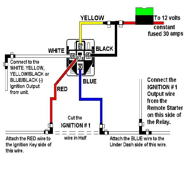
The wiring diagrams of the ignition illustrate the various wires that provide power to the various parts of the car. Typically there are four distinct colored terminals for each part. The red color is used for accessories and yellow is for the battery, and green is the solenoid for starters. The “IGN” terminal lets you start the car, control the wipers or other functions. The following diagram shows how to connect both the ACC terminal as well as the ST terminals to other components.
The battery is connected to the terminal whose name is BAT. The battery is essential for the electrical system to begin. A dead battery could make the switch stop turning on. You can refer to your wiring diagram if you’re not sure where the batteries of your car are located. The accessory terminals of your car are connected to the battery as well as the ignition switch. The BAT terminal is connected to the battery.
Some ignition switches feature an “accessory” setting that allows users to control their outputs , without needing to utilize the ignition. Sometimes, customers wish to use an auxiliary output that is separate from the ignition. It is possible to use the secondary input by connecting it to the ACC terminal. This feature is convenient however it does have one major distinction. A lot of ignition switches can be programmed to have an ACC position when the vehicle has moved into the ACC position. They’ll also be in the START position once the vehicle is moved into the IGN position.
Gallery of 1996 Toyota Corolla Ignition Wiring Diagram
Gallery of 1996 Toyota Corolla Ignition Wiring Diagram


