Ford Ignition Switch Wiring Diagram – We’ll begin by looking at the various types terminals found on an ignition switch. These are the terminals that connect the Ignition, Coil, or Accessory. After we’ve identified the terminals used and which ones are not, we can identify the different components of the Ford Ignition Switch Wiring Diagram. Then, we will discuss the roles of the Ignition switch, as well as the Coil. After that we will move on to the Accessory Terminals.
Terminals for the ignition switch
An ignition switch is comprised of three switches. They supply the voltage of the battery to different locations. The first one supplies power to the choke whenever it is pushed. The third is the switch that controls the ignition’s ON/OFF positions. Different manufacturers have different colour-coding systems that correspond to the conductors. OMC follows this scheme. An additional connector is included in the ignition switch for connecting an Tachometer.
While the majority of the ignition switch terminals may not be original, the numbering for each may not match the diagram. The first step is to check the continuity of each wire to make sure they’re properly plugged into the ignition switches. You can check this using a simple multimeter. After you’ve confirmed the integrity of the wires you can then install the connector. The wiring loom for an ignition switch that’s supplied by the factory will be different from the one in your car.
Before connecting the ACC outputs to the auxiliary outputs of your car It is essential to be familiar with the fundamentals of these connections. The ACC and IGN connectors are the standard connections for your ignition switch. While the START, IGN, and ACC terminals are primary connections to the radio or stereo, the START/IGN connections are the primary ones. The ignition switch regulates the engine in your car. The terminals of older vehicles ignition switches are marked by “ACC” as well as ST (for specific magneto wires).
Terminals for coil
The first step to determine the type of ignition coil is to comprehend the terminology employed. An understanding of the basic wiring diagram for ignition will show you a number of terminals and connections. The coils have a specific operating voltage. The first step to determine which one you have will involve testing the voltage at S1, the primary terminal. To determine if it is an A, C, or B coil you must also check the resistance of S1.
The negative of the chassis must be connected to the side of low-tension. This is what you see in the wiring diagram. The high-tension part connects the spark plugs to a positive. For suppression purposes, the coil’s body metal must be connected with the chassis. This is not necessary for electrical use. You will also see the connections of the positive and negative coil’s terminals on the diagram of the ignition wiring. In some instances it is possible to find the ignition coil is damaged and is easily identified with a scan in an auto parts store.
The black-and-white-striped wire from the harness goes to the negative terminal. The positive terminal is connected to the white wire with the trace of black. The black wire connects to the contactbreaker. If you’re not sure about the connections of both, you can use an old paper clip to take them from the plug housing. Also, make sure to verify that the connections aren’t bent.
Accessory terminals
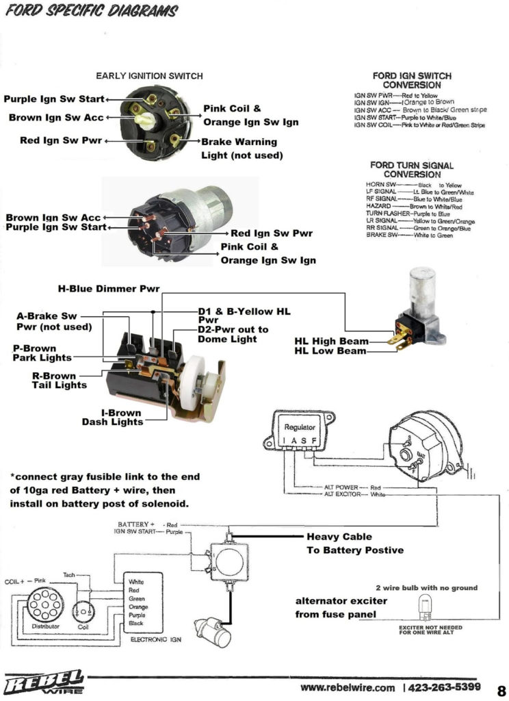
The diagrams for ignition wiring depict the wires that are used to power the vehicle’s electrical supply. There are usually four terminals with color codes that are connected to the respective component. Red is for accessories and yellow is for the battery, while green is the starter solenoid. The “IGN” terminal is used to turn on the car, turn on the wipers, as well as other features. This diagram demonstrates how to connect ACC and ST terminals to the rest of the components.
The terminal BAT is the connector for the battery. The electrical system can’t begin without the battery. Additionally, the switch will not be able to turn on without the battery. It is possible to view your wiring diagram to figure out where your car’s batteries are placed. The accessory terminals of your car are connected to the ignition switch, as well as the battery. The BAT terminal connects to the battery.
Some ignition switches feature an additional “accessory” location, which allows users can control their outputs with no ignition. Users may wish to utilize the auxiliary output separately from the ignition. In order for the auxiliary output be used, connect the connector in the same shade as the ignition. Then , connect it to the ACC end of the switch. While this is an excellent feature, there’s something you need to know. The majority of ignition switches are configured to have an ACC status when the car is at the ACC or START positions.
Gallery of Ford Ignition Switch Wiring Diagram
Gallery of Ford Ignition Switch Wiring Diagram


