6 Terminal Ignition Switch Wiring Diagram – Let’s first examine the different types and purposes of the terminals that are found on the ignition switches. These are the terminals that connect the Ignition, Coil, or Accessory. Once we’ve determined the function of the terminals we can recognize the various parts of the ignition wiring. We’ll also go over the functions of the Ignition switch and Coil. We’ll then turn our attention to the accessory terminals.
Terminals of ignition switch
Three switches are found in an ignition switch. Each of these switches feeds the battery’s voltage to various places. The first switch provides power to the choke while the second switch controls the on/off status of the ignition switch. Every manufacturer has its individual color-coding system that we’ll go over in a separate article. OMC utilizes this method. This connector allows the connection of a speedometer to the ignition switch.
While many ignition switch terminals could not be original, the numbering of each one might not be in line with the diagram. You should first check the electrical continuity to ensure that they are connected to the ignition switch correctly. This can be done using a simple multimeter. After you’re sure that the wires are in good continuity, you can attach the new connector. If your vehicle has an original ignition switch supplied by the factory (or a wiring loom) The wiring loom might differ from that of your vehicle.
You must first understand the way that ACC outputs and auxiliary outputs function in order to join them. The ACC/IGN connections function as the default connection on the ignition switch. The START/IGN terminals are connected to the stereo or radio. The ignition switch is the one that turns the engine of your car on and off. The terminals of the ignition switch on older cars are identified with the initials “ACC” as well as “ST” (for each magneto wires).
Terminals for coil
The language used to decide the kind and model of the ignition coil is the most important thing. You’ll see a number of connections and terminals in the basic wiring diagram for ignition that include two primary and two secondary. Each coil operates at a specific voltage. The first step to determine the kind you have is to check the voltage at S1 or the primary terminal. S1 should also undergo resistance testing to determine if it are an A or B coil.
The chassis’ negative must be connected to the low-tension side. This is the ground of the ignition wiring. The high-tension side delivers positively direct to the spark plugs. It is essential to suppress the metallic body of the coil is connected to its chassis but not essential. The wiring diagram for ignition will also indicate how to connect the positive coil terminals. Sometimes, a damaged ignition coil can be identified by a scan done at an auto parts shop.
The black-and-white-striped wire from the harness goes to the negative terminal. Positive terminal receives the white wire that has a black trace. The black wire is connected to the contact breaker. To test the wires’ connections, employ a paperclip to lift them out of the housing. It’s also essential to ensure that the terminals do not bend.
Accessory terminals
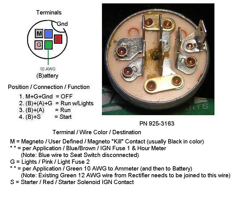
The ignition wiring diagrams show the various wires that are used to power different components. There are typically four colored terminals for each component. The accessories are red, the battery is yellow, and the starter solenoid green. The “IGN terminal” is used to run the wipers, as well as other operating features. This diagram demonstrates how to connect ACC and ST terminals to the rest of components.
The terminal BAT connects the battery to the charger. Without the battery the electrical system can not begin. Furthermore, the switch won’t start. To find your car’s battery examine the wiring diagram. The ignition switch and battery are connected through the accessory terminals. The BAT Terminal is connected to the battery.
Some ignition switches come with an accessory position. This allows users to connect their outputs to another location without the ignition. Sometimes, customers would like the output of the auxiliary to be used independently from the ignition. To make use of the auxiliary output, wire the connector with the same colors as the ignition, and connect it to the ACC terminal on the switch. This is a great feature, however there’s an important difference. The majority of ignition switches have an ACC position when the vehicle is in the ACC however, they’ll be at the START position when the vehicle is in IGN.
Gallery of 6 Terminal Ignition Switch Wiring Diagram
Gallery of 6 Terminal Ignition Switch Wiring Diagram


