Club Car Ds Ignition Switch Wiring Diagram – We will first examine the various types of terminals that are found on the ignition switch. These terminals are for the Ignition button, Coil and Accessory. Once we understand the function of each type of terminal, we are able to identify the parts of the ignition wiring. Then, we will discuss the functions and the Coil. We will then concentrate on the accessory terminals.
Terminals for the ignition switch
The ignition switch consists of three switches. These are the ones that supply the battery’s energy to various places. The first switch is utilized to power the choke through pushing it, while the third switch is used to control the ON/OFF setting. Each manufacturer has their individual color-coding system that we’ll discuss in a subsequent article. OMC uses this method. The ignition switch also includes an option to connect the timer.
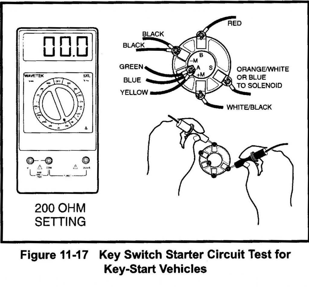
Although some ignition switch terminals could not be original, the numbers of the terminals may not be in line with the diagram. To make sure that your wires are correctly plugged in to the ignition switch, you should check their continuity. This can be done with a cheap multimeter. When you’re satisfied with the continuity of your wires, you’ll be able install the new connector. If you’re using a factory-supplied ignition switch the wiring loom will be distinct from the one that is you have in your car.
Understanding how the ACC outputs connect to the auxiliary outputs inside your vehicle is crucial. The ACC/IGN connections function as the default connections on the ignition switch. The START/IGN terminals are connected to the stereo or radio. The ignition switch regulates the engine in your car. Older cars have the ignition switch’s terminals that are labeled “ACC” or “ST” (for individual magnetowires).
Terminals for coil
The terms used to define the type and model of an ignition coil is the primary thing. You will see several connections and terminals on an ignition wiring schematic which includes two primary and two secondary. Each coil operates at a specific voltage. The first step to determine the kind you’re using is to examine the voltage on S1, or the primary terminal. S1 must also be inspected for resistance in order to identify whether it’s a Type B, B or an A coil.
The negative end of the chassis should be connected to to the coil’s lower-tension end. This is the ground of the ignition wiring. The high-tension side supplies positive direct to the sparkplugs. The aluminum body of the coil needs to be linked to the chassis to prevent it from being smothered but isn’t required. The diagram of the ignition wiring will also outline the connections of the positive coil terminals. Sometimes, a damaged ignition coil can be detected with a scan at an auto repair shop.
The black-and-white-striped wire from the harness goes to the negative terminal. The white wire also is black with a trace, and connects to the positive terminal. The black wire is connected to the contactbreaker. To check the wires’ connections use a paperclip to lift them off the housing. Also, make sure that the connections aren’t bent.
Accessory Terminals
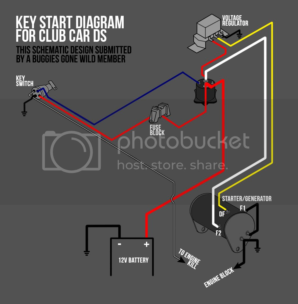
Diagrams of ignition wiring depict the wires that power various parts of the car. There are generally four colored terminals for each component. The accessories are colored red and the battery yellow the starter solenoid green. The “IGN terminal is used to start the car, operating the wipers and various other functions. This diagram shows how to connect ACC and ST terminals to the other components.
The terminal referred to as BAT is the place where the battery is. The electrical system will not start in the event that the battery isn’t connected. In addition, the switch will not begin to turn on. You can view your wiring diagram to figure out the location of your car’s batteries. placed. The accessory terminals in your vehicle are connected to the battery as well as the ignition button. The BAT terminal is connected with the battery.
Certain ignition switches have an accessory setting where users can adjust their outputs as well as control them without having to turn on the ignition. Sometimes, customers may wish to use the auxiliary input separately from the ignition. Make use of the additional output by connecting it to an ACC terminal on your switch using the same colors. This feature of convenience is fantastic however there’s a distinction. Most ignition switches are configured to have an ACC status when the vehicle is in the ACC or START position.
Gallery of Club Car Ds Ignition Switch Wiring Diagram
Gallery of Club Car Ds Ignition Switch Wiring Diagram


