Suzuki 1500 Intruder Ignition Wiring Diagram – First, we will look at the different types of terminals in the ignition switch. These terminals are for the Ignition button, Coil and Accessory. After we’ve established the purpose of these terminals are then we can discover the various components of the Suzuki 1500 Intruder Ignition Wiring Diagram. Then, we will discuss what functions are available for the Ignition switch and the Coil. Then, we’ll turn our attention to Accessory terminals.
Terminals for ignition switch
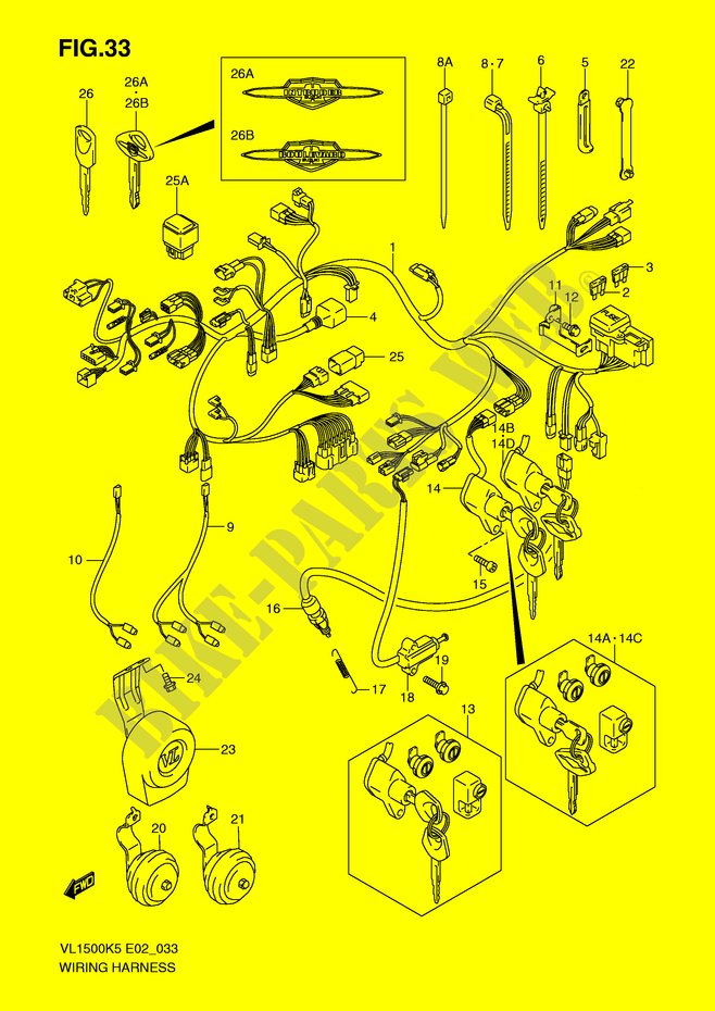
The ignition switch is comprised of three separate switches that feed the battery’s current to various locations. The choke is powered by the first switch. The second switch controls the ON/OFF of the ignition switch. Each manufacturer has their individual color-coding system that we will discuss in another article. OMC employs this system. The ignition switch also includes a connector for adding the tachometer.
Even though most ignition switch terminals don’t have an original number, they may be equipped with a different number. To make sure that the wires are correctly connected to the switch it is recommended to check their continuity. A simple multimeter will assist you in this. Once you’re satisfied with the connection then you can connect the new connector. The wiring loom used in the ignition system switch supplied by the manufacturer is distinct.
Before connecting the ACC outputs to the auxiliary outputs of your car, it is important to understand the basics of these connections. The ACC and IGN terminals are the default connection on the ignition switch. the START and IGN terminals are the main connections for the radio and stereo. The ignition switch controls the car’s engine. Older vehicles have ignition switch terminals marked “ACC” or “ST” (for individual magnetowires).
Coil terminals
Understanding the terminology is the initial step towards knowing what type of ignition coil you’ve got. A basic diagram of the wiring will provide you with a range of terminals and connections. The voltage that operates on each coil is different. This is why it is crucial to test the voltage at the S1 (primary terminal). S1 should be tested for resistance in order to identify if the coil is type A, B and/or C.
The lower-tension side of the coil must be connected to the chassis the negative. It is also the ground on the diagram of ignition wiring. The high-tension part is a positive connection to the sparkplugs. The body of the coil has to connect to the chassis to suppress the effect, but it is not electrically essential. The wiring diagram will show the connection between the positive and negative coils. In some cases it is possible to find a malfunctioned ignition coil is identified by scans in an auto parts store.
The black-and-white-striped wire from the harness goes to the negative terminal. The terminal that is negative is served by the trace in black that’s joined to the white wire. The black wire is connected to the contact breaker. You can remove the black wire from the housing of the plug using a paper clip in case you are uncertain about the connection. It’s also crucial to make sure that the terminals do not bend.
Accessory terminals
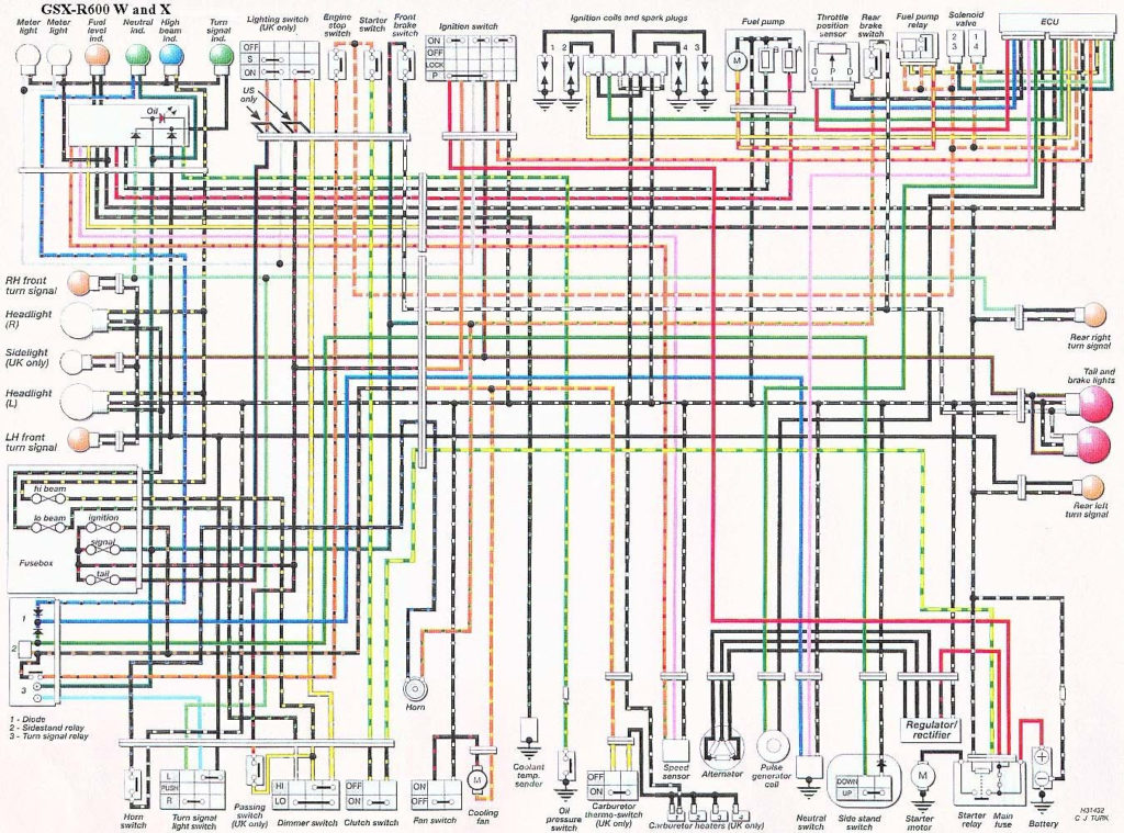
The ignition wiring diagrams illustrate the various wires that power the various components of the vehicle. In general there are four distinct colors-coded terminals that are used for each component. To identify accessories, red is the starter solenoid’s color, yellow is for battery, and blue for accessory. The “IGN terminal” is used to provide power to the wipers and other operating functions. This diagram shows how to connect ACC and ST terminals to the rest of the components.
The terminal BAT is where the battery is. The electrical system cannot begin without the battery. The switch won’t be able to turn on if the battery isn’t there. You can view your wiring diagram to determine the location of your car’s batteries. located. The accessory terminals of your car are connected with the battery and the ignition button. The BAT terminal is connected with the battery.
Certain ignition switches have an accessory setting where users can modify their outputs and control them without needing to use the ignition. Some customers want an auxiliary output that can be used separately from the ignition. For the auxiliary output to be used, plug in the connector to the same color as the ignition. Then , connect it to the ACC end of the switch. This feature is convenient however, it does have one major distinction. Some ignition switches are set to have an ACC position once the car has been moved into the ACC position. They also will be in the START position when the vehicle has moved into the IGN position.
Gallery of Suzuki 1500 Intruder Ignition Wiring Diagram
Gallery of Suzuki 1500 Intruder Ignition Wiring Diagram


