6 Volt Ignition Coil Wiring Diagram – We will first look at the various types of terminals for the ignition switch. These include the terminals that are for the Ignition switch, Coil, and Accessory. Once we know what these kinds of terminals are used for We will then determine the various parts of the 6 Volt Ignition Coil Wiring Diagram. In addition, we will discuss the different functions of the Ignition Switch and Coil. Then, we’ll turn our attention to Accessory terminals.
Terminals for the ignition switch
Three switches can be found in an ignition switch. Each of these switches feeds the battery’s voltage to a variety of places. The first switch provides power to the choke, and the third switch toggles the ON/OFF status of the ignition switch. Different manufacturers have different colors-coding systems to match the conductors. OMC uses this method. The connector allows for the connection of a speedometer to the ignition switch.
While the majority of the ignition switch terminals may not be authentic, the numbering of each might not be consistent with the diagram. Check the integrity of the wires to ensure that they are plugged into the correct ignition switch. A multimeter is a good tool to test the continuity. After you’re satisfied with the integrity of the wires you can connect the new connector. The wiring loom for an ignition switch that’s supplied by the factory will be different from the one you have in your car.
In order to connect the ACC outputs to the auxiliary outputs of your car, you’ll need first know how these two connections work. The ACC, IGN and START terminals are your default connection to the ignition switch. They also serve as the primary connections to the radio and stereo. The ignition switch is the one that turns the car’s engine to and off. Older cars are equipped with ignition switch terminals marked “ACC” or “ST” (for individual magnetowires).
Terminals for coil
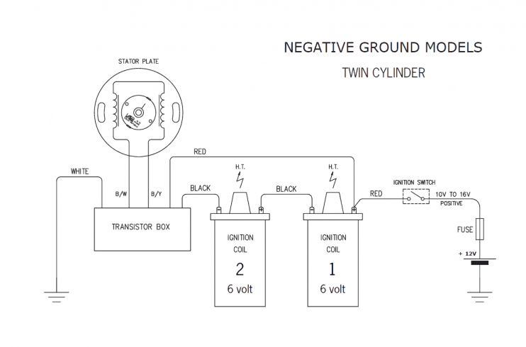
Understanding the terms that is used is the first step to finding out the right type of ignition coil. The fundamental diagram of ignition wiring depicts various connections and terminals. There are two primary and one secondary. The coils are equipped with a particular operating voltage. The first step in determining which type you’re using is to test the voltage on S1, the main terminal. S1 should also undergo resistance tests to determine if it are an A or B coil.
The chassis’ negative needs to be connected to the low-tension side. This is exactly what you can find in the diagram of wiring. The high-tension side supplies positive direct to the sparkplugs. To reduce the noise the body of the coil must be connected to chassis. But, it’s not necessary to connect the coil electrically. The wiring diagram of the ignition will show you how to connect the terminals of either the positive and negative coils. In some cases it is possible to find a malfunctioned ignition coil can be diagnosed with a scan in an auto parts store.
The black-and-white-striped wire from the harness goes to the negative terminal. The terminal that is negative is served by the trace in black that’s connected to the white wire. The black wire goes to the contact breaker. It is possible to check the connections with a paperclip to pull the wires out from the housing. Make sure that the terminals do not bend.
Accessory terminals

Ignition wiring diagrams show the various wires used to power the car’s various components. Each part has four distinct colored connections. Red stands for accessories, yellow represents the battery, and green for the solenoid for starters. The “IGN” terminal is utilized to turn on the car, control the wipers and other functions. The diagram illustrates how you can connect ACC or ST terminals and the rest.
The terminal BAT is the connection for the battery. Without the battery, the electrical system does not start. A dead battery can cause the switch to stop turning on. You can view your wiring diagram to determine where the batteries of your car are situated. The ignition switch and battery are connected by the accessory terminals. The BAT terminal is connected to the battery.
Some ignition switches are equipped with an additional position. This allows users to access their outputs from another location without having to turn on the ignition. Customers sometimes want an auxiliary output that can be used independently from the ignition. In order to use the auxiliary output, connect the connector using the same colors as the ignition and connect it to the ACC terminal on the switch. Although this is a useful feature, there’s one important difference. Most ignition switches will be in an ACC position when the vehicle is in the ACC, but they’ll be in the START position when the vehicle is IGN.
Gallery of 6 Volt Ignition Coil Wiring Diagram

Gallery of 6 Volt Ignition Coil Wiring Diagram


