69 Chevy C10 Ignition Wiring Diagram – We’ll begin by looking at the various types of terminals in an ignition switch. These include the terminals for the Ignition switch, Coil, and Accessory. Once we have identified what these terminals are and what they do, we can then determine the various components in the ignition wiring. We’ll also go over what functions are available for the Ignition switch as well as the Coil. After that we will discuss the Accessory Terminals.
Ignition switch terminals
An ignition switch has three different switches that direct the battery’s current to various destinations. The first one is used to power the choke through pushing it, while another switch controls the ON/OFF position. Different manufacturers use different colour-coding systems that correspond to the conductors. OMC utilizes the same system. Connectors can be connected to the ignition switch in order to include an electronic Tachometer.
Even though most ignition switch terminals don’t carry an original number, they may have a different one. It is important to first verify the electrical continuity to determine if they’re plugged into the correct ignition switch. A simple multimeter will help you do this. Once you are satisfied that all wires are in good continuity then you can connect the new connector. The wiring loom of the ignition switch factory-supplied will be different than the one that you have in your car.
Before connecting the ACC outputs to the auxiliary outputs of your car it is crucial to know the fundamentals of these connections. The ACC and IGN connectors are the default connections for your ignition switch. The START, IGN, and ACC terminals are the main connections to the radio or stereo, the START/IGN terminals are the most important ones. The ignition switch controls the car’s engine. Older cars are equipped with ignition switch terminals labeled “ACC” or “ST” (for individual magnetowires).
Terminals for coil
Understanding the terminology is the initial step in knowing what type of ignition coil you’ve got. You’ll see a number of connections and terminals on the basic wiring diagram for ignition which includes two primary as well as two secondary. Each coil is equipped with a distinct operating voltage. To determine what kind of coil you’ve got the first step is to check the voltage at S1, the primary terminal. S1 must be checked for resistance to identify if the coil is type A, B and/or C.
The coil’s low-tension component is to be connected to the chassis’ positive. This is the ground on the ignition wiring diagram. The high-tension side supplies the spark plugs with positive. The coil’s metal body needs to be connected to the chassis for suppression purposes, but it is not electrically necessary. There are also connections between the positive and negative coil’s terminals on the ignition wiring diagram. Sometimes, an inspection at an auto part store can identify a problem with the ignition wire.
The black-and-white-striped wire from the harness goes to the negative terminal. The white wire also is black with a trace on it, and connects to the positive terminal. The black wire connects with the contact breaker. To check the connections, use a paperclip or a pencil to lift them out of the housing for the plug. It’s also crucial to ensure that the terminals aren’t bent.
Accessory terminals
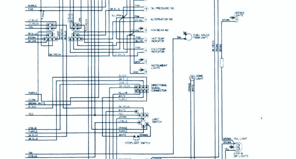
Diagrams of ignition wiring show the wires that power various parts of the vehicle. There are generally four colors of terminals connected to each part. The red color is used for accessories and yellow is for the battery, while green is for the starter solenoid. The “IGN terminal” is used to power the wipers and other operating functions. The diagram shows the connection of the ACC- and ST terminals.
The terminal BAT is the connection to the battery. The battery is essential to allow the electrical system to begin. In addition, the switch doesn’t turn on. It is possible to look up the wiring diagram of your car to see the location of your car’s batteries. situated. The accessory terminals on your car connect to the battery and the ignition switch. The BAT terminal is connected to the battery.
Certain ignition switches come with an accessory position where users can alter their outputs and control them without having to turn on the ignition. Customers sometimes want the auxiliary output to be used separately from the ignition. You can use the secondary input by connecting the connector to the ACC terminal. This is a convenient feature however, it does have one major distinction. Many ignition switches can be configured to be in an ACC position when the vehicle has moved into the ACC position. They also will be in the START mode after the vehicle has been moved into the IGN position.
Gallery of 69 Chevy C10 Ignition Wiring Diagram
Gallery of 69 Chevy C10 Ignition Wiring Diagram


