67 Camaro Ignition Switch Wiring Diagram – Let’s begin by examining the different types and functions of the terminals that are found in the ignition switches. These terminals comprise the Ignition switch and Coil and the Accessory. Once we’ve established the purpose of the terminals we can recognize the various parts of the ignition wiring. We’ll also be discussing the functions of the Ignition switch and Coil. After that, we’ll turn our attention to Accessory terminals.
The ignition switch’s terminals
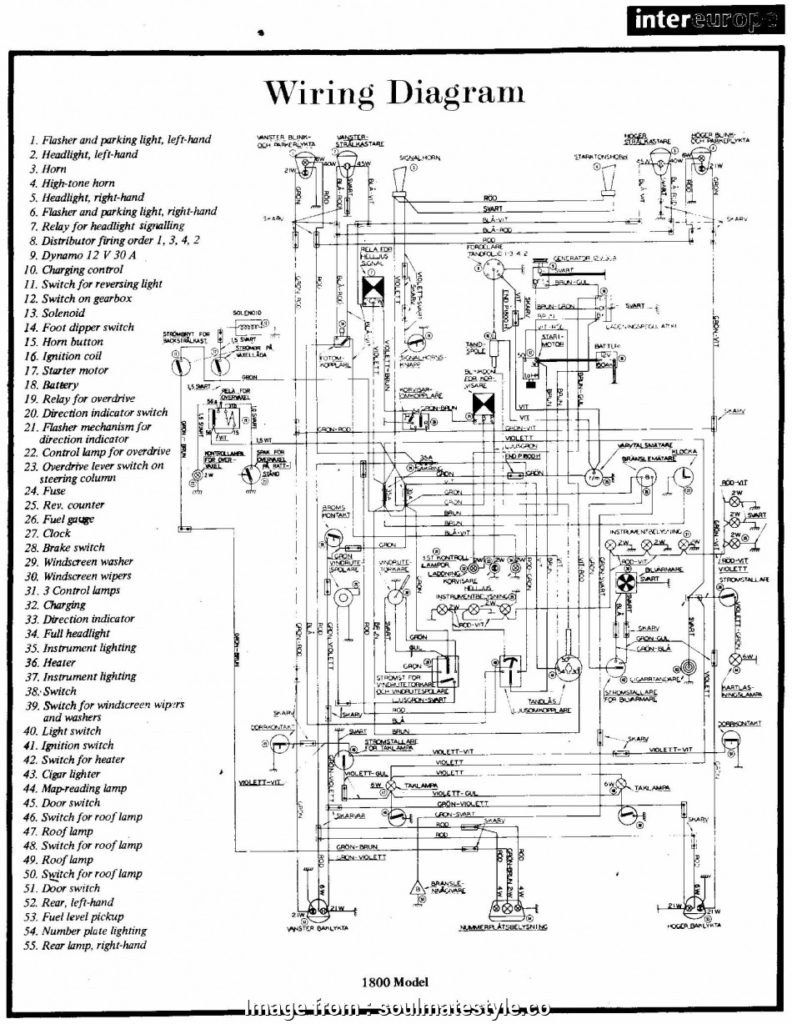
An ignition switch is made up of three switches. They are responsible for feeding the battery’s power to several places. The first one is utilized to drive the choke through pushing it. Then, the second is for the ON/OFF position. Different manufacturers use different color codes for different conductors. This is explained in a different article. OMC utilizes this method. Connectors can be attached to the ignition switch to connect an electronic Tachometer.
While the majority of the ignition switch terminals are not original, the numbering for each may not match the diagram. Check the continuity of all the wires to ensure they are correctly connected to the ignition switches. This can be checked with a simple multimeter. After you’re satisfied with the connection then you can connect the new connector. The wiring loom of an ignition system switch that is supplied by the manufacturer is different.
Before you can connect the ACC outputs to your car’s auxiliary outputs it is crucial to understand the basics of these connections. The ACC/IGN terminals function as the default connections for the ignition switch. The START/IGN terminals connect to the stereo or radio. The ignition switch’s function is for turning the car’s engine on and off. The terminals of older cars ignition switches are identified by “ACC” and ST (for individual magneto wires).
Coil terminals
To determine the type of ignition coil you need to know the step is to know the terms. There are a variety of connections and terminals within the basic wiring diagram for ignition, including two primary, and two secondary. The voltage that operates on each coil is different. This is why it is essential to first check the voltage at the S1 (primary terminal). To determine whether it’s an A, C or B coil, it is recommended to also check the resistance of S1.
The lower-tension side of the coil needs to be connected to the chassis’ negative. This is what is known as the ground for the ignition wiring. The high tension side provides positive directly the spark plugs. It is necessary to suppress the coil’s metallic body be connected to the chassis, however it isn’t essential. The diagram for the ignition wiring will also reveal the connections between the negative and positive coil’s terminals. In some cases you’ll discover that a malfunctioned ignition coil can be diagnosed with scans at an auto parts store.
The black-and-white-striped wire from the harness goes to the negative terminal. The white wire also has a black trace on it, and connects to the positive terminal. The black wire connects to the contact breaker. To check the connections between the two wires, use a paperclip and lift them off the housing. It is also important to make sure the terminals don’t bend.
Accessory terminals
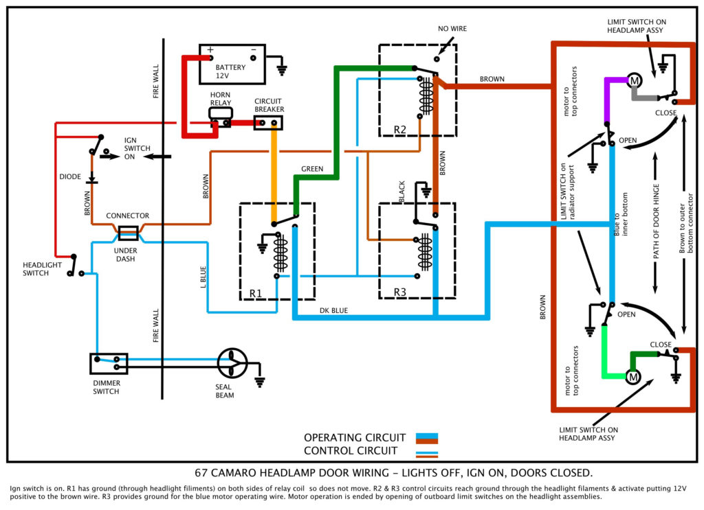
The wiring diagrams for the ignition show the different wires used to are used to power various components of the car. There are usually four different colored terminals for each component. For accessories, red is for starter solenoid, blue for battery, and blue is for accessories. The “IGN terminal” is used to run the wipers, as well as other operating features. The diagram illustrates how to connect ACC or ST terminals as well as the rest.
The terminal BAT connects the battery to the charger. The battery is essential to allow the electrical system to get started. Additionally the switch won’t come on. The wiring diagram will tell the location of your car’s battery. The ignition switch and battery are connected via accessory terminals. The BAT connector is connected to the battery.
Some ignition switches come with an additional “accessory position” which allows users to alter their outputs without the ignition. Some customers prefer to utilize an additional output independent of the ignition. In order to use the additional output, wire the connector with the same colors as the ignition, connecting it to the ACC terminal on the switch. This feature is convenient however, it does have one significant differentiator. A majority of ignition switches feature an ACC position when your vehicle is in ACC mode and a START position when you are in IGN.
Gallery of 67 Camaro Ignition Switch Wiring Diagram
Gallery of 67 Camaro Ignition Switch Wiring Diagram


