Dodge Ignition Wiring Diagram – Let’s first take a look at the different types of terminals that are used in the ignition switch. They are terminals that are used for Coil, Ignition Switch, and Accessory. Once we have identified the terminals that are utilized then we can recognize the various parts of the Dodge Ignition Wiring Diagram. We’ll also discuss the functions as well as the Coil. After that we will proceed to the Accessory Terminals.
The terminals of the ignition switch
Three switches can be found in an ignition switch. Each of these switches feeds the battery’s voltage to several different places. The ON/OFF state of the ignition switch is controlled by the third switch, which provides power to the choke when it is pushed. Different manufacturers have different color codes for different conductors. This is discussed in a different article. OMC uses the same method. The ignition switch comes with a connector for adding an timer.
While many ignition switch terminals don’t have the original design The numbering might not match that of the diagram. To make sure that your wires are correctly plugged in to the switch, you must verify their continuity. A multimeter is an excellent tool to check the continuity. When you’re satisfied with the continuity of your wires, you will be able to connect the new connector. If you have an ignition switch supplied by the manufacturer the wiring loom may be different from that you have in your car.
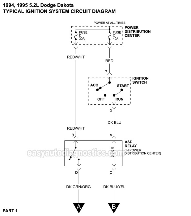
Understanding how the ACC outputs connect to the auxiliary outputs in your car is essential. The ACC, IGN and START terminals are the primary connections to the ignition switch. They also function as the primary connections to your radio and stereo. The ignition switch is responsible for turning the car’s engine on and off. Older cars are identified with the initials “ACC”, “ST”, (for individual magneto cables) at their ignition switch terminals.
Terminals for coil
Understanding the terminology is the first step in knowing what type of ignition coil you’ve got. The diagram of the basic ignition wiring depicts various connections and terminals. There are two primary and one secondary. You need to determine the type of coil you are using by testing the voltage at the primary terminal S1. S1 should also be tested for resistance to determine if the coil is a Type B, B or A coil.
The negative of the chassis must be connected to the low-tension side. This is also the ground in the wiring diagram for ignition. The high-tension supply supplies positively directly to spark plugs. For suppression purposes the body of the coil is required to be connected to the chassis. However, it is not required to connect electrically. The ignition wiring diagram will also indicate the connection of the positive coil terminals. In some cases it is possible to find the ignition coil is damaged and is easily identified with scans at an auto parts shop.
The black-and-white-striped wire from the harness goes to the negative terminal. The other white wire has a black color and connects to the terminal opposite. The black wire connects to the contactbreaker. You can take the black wire from the housing of the plug with a paper clip If you’re unsure of the connections. Make sure that the connectors do not bend.
Accessory terminals
Diagrams of ignition wiring show the different wires that are used to power the car’s various components. There are generally four color-coded terminals to each component. Red refers to accessories, yellow the battery and green for the starter solenoid. The “IGN” terminal is utilized to turn on the car, control the wipers and other functions. This diagram demonstrates how to connect ACC and ST terminals to the rest of components.
The terminal BAT is where the battery is. Without the battery, the electrical system does not begin. Also, the switch won’t start without the battery. It is possible to refer to your wiring diagram if you are not sure where the batteries of your car are located. The accessory terminals of your vehicle are connected to the battery as well as the ignition button. The BAT connector is connected to your battery.
Certain ignition switches come with the “accessory” position that allows users to control their outputs without needing to turn on the ignition. Sometimes, customers may wish to use the auxiliary input independently of the ignition. You can use the secondary output by connecting it to the ACC terminal on your switch using the same colors. This is a great convenience feature however, there’s one difference. Most ignition switches are set to operate in the ACC position when the vehicle is in the ACC position, while they’re in the START position when the car is in the IGN position.
Gallery of Dodge Ignition Wiring Diagram
Gallery of Dodge Ignition Wiring Diagram


