John Deere 7 Terminal Ignition Switch Wiring Diagram – Let’s start by looking at the different types of terminals in an ignition switch. These include the terminals for the Ignition switch, Coil, and Accessory. Once we have identified what these terminals are then we can be able to identify the various parts of the ignition wiring. In addition, we will discuss the roles of the Ignition switch, as well as the Coil. After that, we’ll turn our attention to the Accessory terminals.
The terminals are for ignition switches.
An ignition switch has three switches. They supply the battery’s voltage to many different places. The choke is powered by the first switch. The second switch controls the ON/OFF function of the ignition switch. Different manufacturers have different color-coding systems to identify different conductors. This will be covered in a different article. OMC uses this method. The ignition switch comes with a connector for adding a Tachometer.
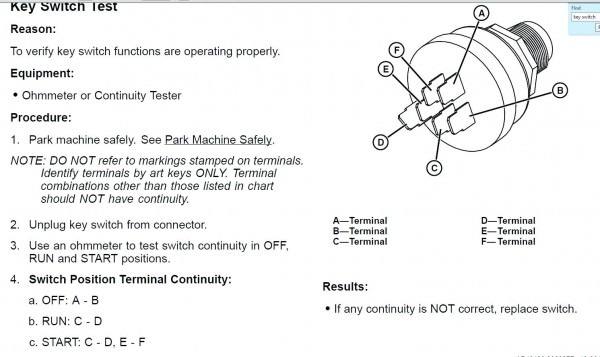
While most ignition switch terminals are duplicated, the number may not be in line with the diagram. You should first check the continuity of the wires to determine if they’re plugged into the correct ignition switch. This can be accomplished using a cheap multimeter. After you’re satisfied with the connection it’s time to connect the new connector. If you are using an ignition switch supplied by the manufacturer, the wiring loom is different from the one used in your vehicle.
It is important to understand the ways in which the ACC outputs and the auxiliary outputs work in order to connect them. The ACC terminals and IGN terminals serve as the default connections to your ignition switch. The START and IGN connections are the primary connections for radio and stereo. The ignition switch switches the engine of your car ON and OFF. The terminals of the ignition switch on older vehicles are marked with the alphabets “ACC” as well as “ST” (for the individual magneto wires).
Coil terminals
Understanding the terms is the first step to knowing what type of ignition coil you’ve got. A basic diagram of the wiring will provide you with a range of connections and terminals. Each coil is operating at a certain voltage. The first step to determine the kind of coil you’re dealing with is to test the voltage at S1 or the primary terminal. To determine if it is a Type A, C or B coil, you must also check the resistance of S1.
The negative of the chassis must be connected to the low-tension side. This is the ground in the wiring diagram for ignition. The high-tension supply provides positive directly to spark plugs. To prevent noise the coil’s metal body must be connected with the chassis. This is not necessary for electrical use. It is also possible to see the connections of the negative and positive coil terminals on the ignition wiring diagram. It is possible to find an issue with the ignition coil that can be easily diagnosed by looking it up at an auto parts store.
The black-and-white-striped wire from the harness goes to the negative terminal. The positive terminal also receives a second white wire, which is black in its trace. The black wire connects to the contact breaker. To check the connections between the two wires, use a paperclip to lift them from the housing. Check that you don’t bend the connectors.
Accessory Terminals
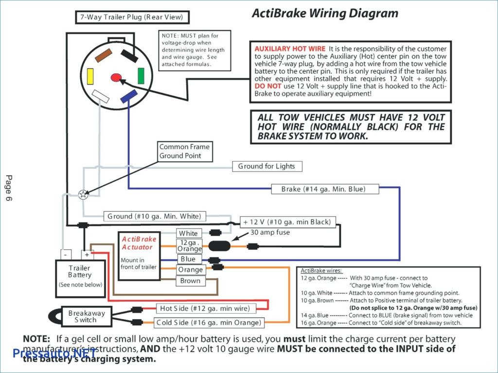
Ignition wiring diagrams depict the various wires that are used to power different components. Each component is equipped with four distinct color-coded connections. For accessories, red stands for starter solenoid, yellow for battery, and blue for accessories. The “IGN” terminal is used to turn on the vehicle and control the wipers as well as other operational features. This diagram shows how to connect ACC and ST terminals to the rest of the components.
The terminal BAT is where the battery is. The electrical system will not start without the battery. In addition the switch won’t come on. The wiring diagram will tell you where to find the battery in your car. The ignition switch is connected to the battery of your car. The BAT terminal is connected with the battery.
Certain ignition switches provide the option of an “accessory position” that allows users to modify their outputs independent of the ignition. Sometimes, users want to use an auxiliary output independent of the ignition. The auxiliary output could be utilized by wiring the connector with the same colors as the ignition, and then attaching it to the ACC terminal of the switch. This option is useful, but it has one major difference. Most ignition switches will have an ACC position if the car is in ACC however they’ll be at the START position when the vehicle is IGN.
Gallery of John Deere 7 Terminal Ignition Switch Wiring Diagram
Gallery of John Deere 7 Terminal Ignition Switch Wiring Diagram


