Holley Hyperspark Ignition Box Wiring Diagram – In the beginning, we’ll examine the various types of terminals that are found on the ignition switch. These terminals include the Ignition switch as well as the Coil along with the Accessory. Once we understand the function of each type of terminal, we can then determine the components of the ignition wiring. We’ll also discuss the functions as well as the Coil. Then, we’ll turn our attention to Accessory terminals.
Terminals of ignition switch
Three switches can be found on an ignition switch. Each of these switches feeds the battery’s voltage to several different destinations. The first one is utilized to turn on the choke through pushing it. Then, the second is for the ON/OFF setting. Different manufacturers use different colors for various conductors. This is described in another article. OMC utilizes this system. There is a connector in the ignition switch to allow attaching a tachometer.
While the majority of the ignition switch terminals are not original, the numbering for each one may not be in line with the diagram. Check the continuity of the wires first to make sure they’re connected correctly to the ignition switch. A multimeter is a good instrument to verify the continuity. After you’re satisfied with the continuity of the wires it is time to install the new connector. The wiring loom used in a factory-supplied ignition system switch differs.
Before you can connect the ACC outputs to the auxiliary outputs of your car It is essential to understand the basics of these connections. The ACC terminals and IGN terminals function as the default connections to your ignition switch. The START and IGN connections are the main connections for radio and stereo. The ignition switch turns the car’s engine on and off. Older vehicles are identified with the alphabets “ACC”, “ST”, (for individual magneto cables) at their ignition switch terminals.
Coil terminals
Understanding the terminology is the first step towards knowing what type of ignition coil you own. The diagram of the basic ignition wiring illustrates a variety of connections and terminals. There are two primary and one secondary. It is essential to identify the type of coil that you own by examining the voltage at the primary terminal, S1. S1 should be examined for resistance to identify if the coil belongs to type A, B and/or C.
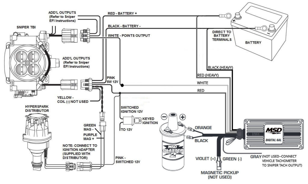
The coil’s low-tension side should be connected at the chassis’ minus. This is the ground on the wiring diagram for ignition. The high-tension end is a positive connection to the sparkplugs. The coil’s metal body needs to connect to the chassis to prevent it from being smothered, but it is not electrically required. The diagram for the ignition wiring will also show you how to connect the positive and negative coil terminals. Sometimes, a damaged ignition coil can be detected through a scan performed at an auto repair shop.
The black-and-white-striped wire from the harness goes to the negative terminal. The white wire has a black color and connects to the negative terminal. The black wire connects to the contact breaker. It is possible to check the connections using a paperclip to pull the wires out from the housing. Also, ensure that the terminals aren’t bent.
Accessory terminals
Diagrams of the ignition wiring illustrate the wiring used to supply power to different parts of the car. There are typically four color-coded terminals that correspond to the component. The accessories are red and the battery yellow the starter solenoid is green. The “IGN terminal is used to start the car, controlling the wipers, and for other functions. The diagram illustrates the connection of the ACCas well as ST terminals.
The battery is connected to the terminal called BAT. The electrical system will not start if the battery isn’t connected. The switch won’t turn on if there is no battery present. You may refer to the wiring diagram if unsure where your car’s batteries are located. Your car’s accessory terminals connect to the ignition switch as well as the battery. The BAT connector is connected to the battery.
Some ignition switches have the “accessory” position that permits users to regulate their outputs without needing to utilize the ignition. Some customers might want to use the auxiliary input independently of the ignition. Use the auxiliary output by connecting it to an ACC terminal on the switch that has the same color. While this is a convenient feature, there is one crucial distinction. Most ignition switches will be in an ACC position when the vehicle is in ACC however, they will be at the START position when the car is in IGN.
Gallery of Holley Hyperspark Ignition Box Wiring Diagram

Gallery of Holley Hyperspark Ignition Box Wiring Diagram


