68 Mustang Ignition Switch Wiring Diagram – Let’s first examine the different kinds and functions of terminals that are found on the ignition switches. These terminals comprise the Ignition switch, the Coil along with the Accessory. Once we have established what these types of terminals are for We will then determine the various parts of the 68 Mustang Ignition Switch Wiring Diagram. We’ll also discuss the functions as well as the Coil. Then, we’ll turn our attention to the Accessory terminals.
Terminals for ignition switch
The ignition switch is comprised of three separate switches that feed the battery’s current to various locations. The ON/OFF state of the switch that controls the ignition is managed by the third switch, which provides the choke with power when it’s pushed. Different manufacturers use different colors-coding systems to match the conductors. OMC uses this approach. The adapter is attached to the ignition switch, allowing the installation of the tachometer.
Although some ignition switch terminals do not appear in their original configuration The numbering might not match that of the diagram. To make sure that the wires are plugged in to the ignition switch you must verify their continuity. You can do this with a simple multimeter. Once you’ve verified the integrity of the wires you can then install the connector. If your car has an original factory-supplied ignition switch (or wiring loom), the wiring loom will differ from that of your vehicle.
Before you can connect the ACC outputs to your car’s auxiliary outputs It is essential to understand the basics of these connections. The ACC and IGN terminals are the default connections for your ignition switch. the START and IGN terminals are the primary connections to the stereo and radio. The ignition switch switches the car’s engine ON and OFF. Older vehicles have ignition switch terminals labeled “ACC” or “ST” (for individual magnetowires).
Terminals for coil
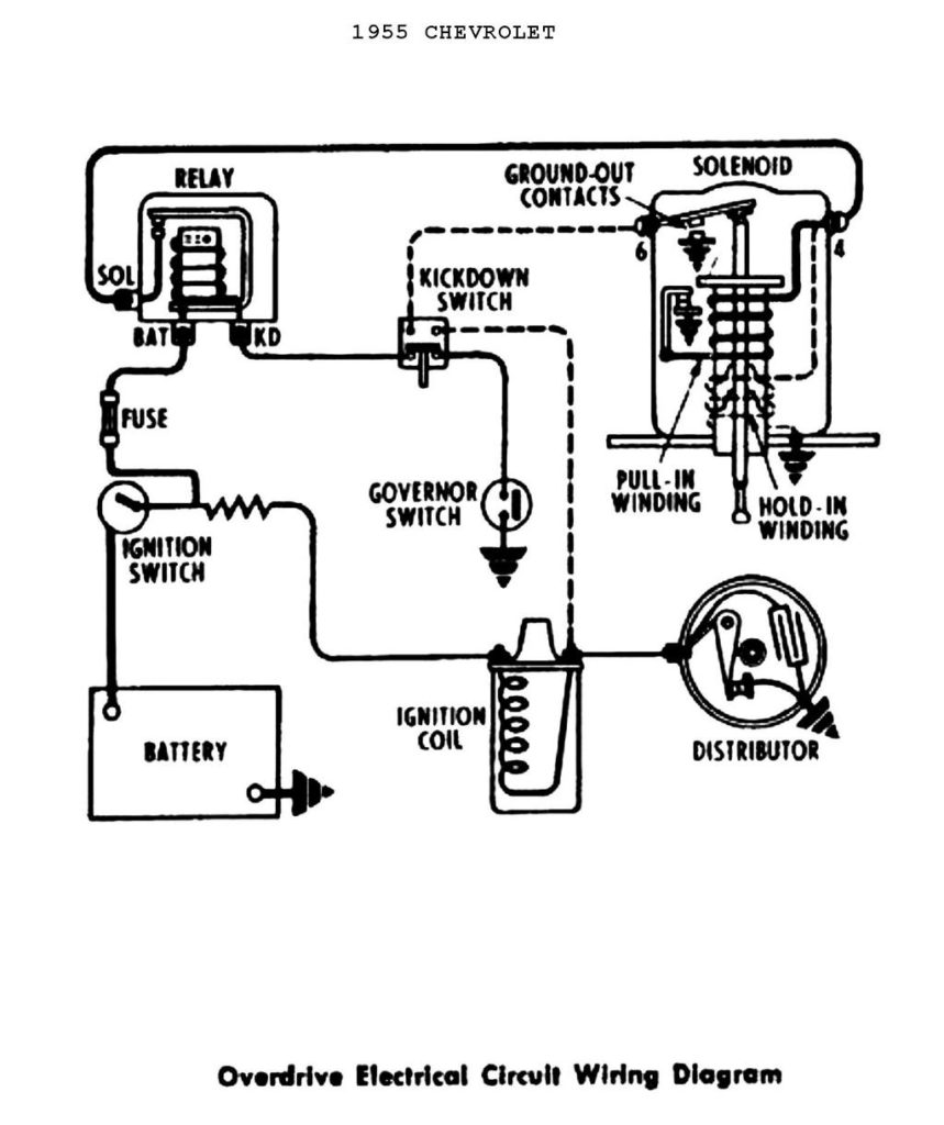
The language used to decide the kind and model of the ignition coil is the first thing. The fundamental diagram of ignition wiring illustrates a variety of connections and terminals. There are two primary and secondary connections. The operating voltage of every coil is different. Therefore, it is important to first test the voltage at S1 (primary terminal). To determine if the coil is an A, C or B coil, you must also check the resistance of S1.
The chassis’ negative needs to be connected to the side of low-tension. This is the ground on the wiring diagram for ignition. The high-tension supply delivers positively directly to spark plugs. For suppression purposes the coil’s body metal is required to be connected to the chassis. It is not required for electrical use. The wiring diagram of the ignition will explain how to connect the terminals of the negative or positive coils. In certain instances scanning your local auto parts shop will be able to diagnose the malfunctioning ignition coils.
The black-and-white-striped wire from the harness goes to the negative terminal. The positive terminal receives the other white wire and a trace of black. The black wire is connected to the contactbreaker. You can remove the black wire from the housing of the plug by using a paperclip if you are unsure about the connections. Make sure the terminals aren’t bent.
Accessory Terminals
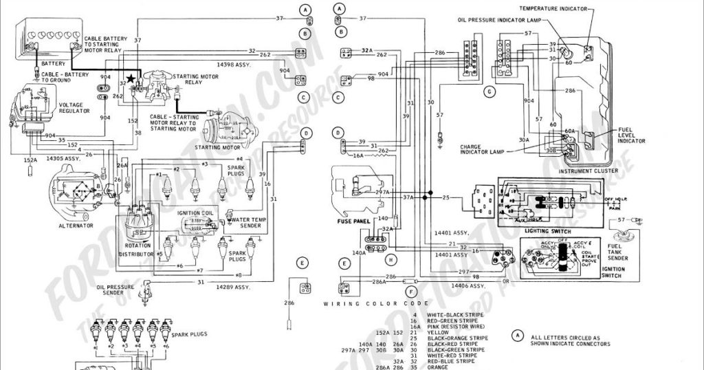
Diagrams of ignition wiring show the different wires that are utilized to power the vehicle’s various parts. There are usually four different color-coded terminals to each component. Red is for accessories, yellow is for the battery, and green is the solenoid for starters. The “IGN” terminal is used for starting the car, operating the wipers and various other functions. The following diagram illustrates how to connect the ACC terminal and ST terminals to various components.
The terminal BAT is where the battery is. Without the battery the electrical system will not begin. Additionally, the switch won’t start. It is possible to look up your wiring diagram to determine where your car’s batteries are placed. The accessory terminals on your vehicle connect to the battery and the ignition switch. The BAT Terminal is connected to the Battery.
Some ignition switches offer the option of an “accessory position” that allows users to adjust their outputs independently of the ignition. Sometimes, customers want to make use of an additional output that is not connected to the ignition. In order for the auxiliary output be used, connect the connector with the same color as the ignition. Connect it to the ACC end of the switch. This is an excellent feature, however there’s one important difference. Most ignition switches will be in an ACC position if the car is in ACC however, they’ll be at the START position when the vehicle is in IGN.
Gallery of 68 Mustang Ignition Switch Wiring Diagram
Gallery of 68 Mustang Ignition Switch Wiring Diagram


