Wiring Diagram For Ignition Switch On Mercury Outboard – Let’s first look at the different terminals on the ignition switch. These include the terminals for the Ignition switch, Coil, and Accessory. Once we understand the function of each terminal, it is possible to identify the parts of the ignition wiring. We will also talk about the functions and the Coil. After that we will proceed to the Accessory Terminals.
The ignition switch’s terminals
An ignition switch is composed of three switches. They are responsible for supplying the battery’s power to various destinations. The first switch provides power to the choke when it is pushed. The second is the ignition switch’s ON/OFF position. Different manufacturers have different color codes for different conductors. This is described in a separate article. OMC utilizes this system. The ignition switch is also equipped with a connector for adding the tachometer.
Even though some ignition switch terminals do not have the original design, the numbering may not be in line with the diagram. Check the electrical continuity first to ensure that they’re properly connected to the ignition switch. A multimeter is a great tool to test the continuity. Once you’re satisfied about the continuity of your wires, you will be able install the new connector. If you have a factory-supplied ignition switch the wiring loom will be distinct from the one that is in your car.
In order to connect the ACC outputs to the auxiliary outputs on your car, you’ll need to first understand the way these two connections function. The ACC and IGN terminals are the default connections for your ignition switch. the START and IGN terminals are the primary connections to the stereo and radio. The ignition switch operates the engine’s off/on button. The ignition switch terminals on older cars are labeled with the alphabets “ACC” as well as “ST” (for the individual magneto wires).
Terminals for Coil
The first step to determine the type of ignition coil is to understand the terms used. You’ll see a number of connections and terminals within a basic ignition wiring schematic, including two primary, as well as two secondary. Each coil has a specific operating voltage. To determine what kind of coil you have the first step is to determine the voltage at S1, the primary terminal. It is also recommended to examine S1 for resistance in order to determine whether it is a Type A or B coil.
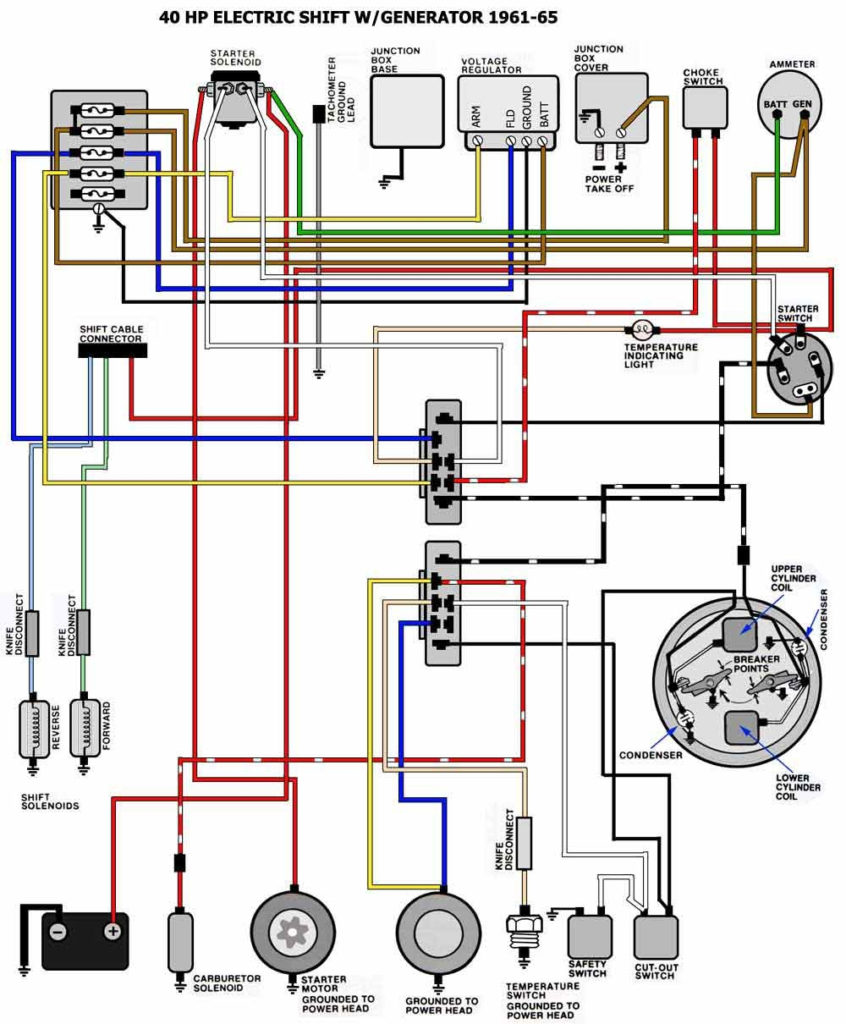
The low-tension end of the coil must be connected to the chassis”negative. This is exactly what you can see on the diagram of wiring. The high tension side provides positively directly to the spark plugs. To reduce the noise the coil’s body metal must be connected with the chassis. It is not required for electrical use. The ignition wiring diagram will also outline the connections of the positive coil’s terminals. In certain cases, a scan at the local auto parts store can help you identify malfunctioning ignition coils.
The black-and-white-striped wire from the harness goes to the negative terminal. The positive terminal receives the white wire with a black trace. The contact breaker is attached to the black wire. You can check the connections with a pencil to remove the wires of the housing. Check that the terminals aren’t bent.
Accessory Terminals
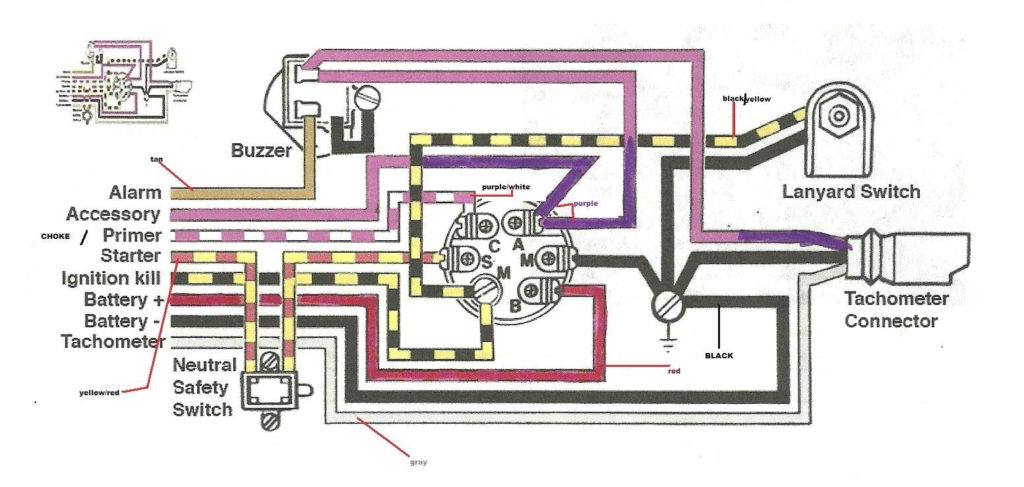
Diagrams of the ignition wiring show the wires that power various parts of the vehicle. Typically, there are four different colors-coded terminals that are used for each component. For accessories, red stands the starter solenoid’s color, yellow is for battery and blue for accessories. The “IGN” terminal allows you to start the car, manage the wipers or other functions. The diagram shows how you can connect the ACC and ST terminals to the rest of the components.
The terminal BAT connects the battery to the charger. Without the battery the electrical system will not get started. A dead battery could cause the switch to not come on. To find the battery in your car examine the wiring diagram. The accessory terminals in your car are connected to the battery and ignition button. The BAT connector is connected to the battery.
Some ignition switches feature an “accessory” position that allows users to regulate their outputs without needing to turn on the ignition. Sometimes, customers would like the auxiliary output to be used separately from the ignition. To allow the auxiliary output to be used, connect the connector with the same shade as that of the ignition. Connect it to the ACC end of the switch. This option is useful however it does have one major difference. The majority of ignition switches are set to operate in the ACC position when the vehicle is in the ACC position, while they’re set to the START position when the car is in the IGN position.
Gallery of Wiring Diagram For Ignition Switch On Mercury Outboard
Gallery of Wiring Diagram For Ignition Switch On Mercury Outboard


