7 Pin Ignition Switch Wiring Diagram – Let’s first examine the different types and purposes of the terminals in the ignition switches. These include the terminals that are for the Ignition switch, Coil, and Accessory. Once we know which terminals are used, we can begin to identify the different components of the 7 Pin Ignition Switch Wiring Diagram. We’ll also be discussing the function of the Ignition switch, and Coil. After that, we will turn our attention towards the accessories terminals.
Terminals for ignition switches
The ignition switch is comprised of three separate switches that feed the battery’s current to various locations. The first switch supplies power to the choke, while the second toggles the status of the ignition switch. Different manufacturers have different color-coding schemes for different conductors. We’ll discuss this in a different article. OMC uses this system. A connector is also included in the ignition switch to allow attaching the Tachometer.
While the majority of the ignition switch terminals aren’t original, the numbers for each one may not be in line with the diagram. Examine the continuity of the wires first to ensure that they’re connected correctly to the ignition switch. You can check this using an inexpensive multimeter. Once you’ve verified that the wires are in good condition, you can then connect the connector. If your vehicle has an original ignition switch supplied by the factory (or wiring loom) the wiring loom will differ from that of your car.
Before you can connect the ACC outputs to the auxiliary outputs of your car, it is important to know the fundamentals of these connections. The ACC and IGN terminals are the default connection on your ignition switch. the START and IGN terminals are the primary connections for radio and stereo. The ignition switch is accountable to turn the car’s engines on and off. Older cars have the ignition switch terminals marked “ACC” or “ST” (for individual magnetowires).
Terminals for coil
Understanding the terms is the first step to knowing what type of ignition coil you have. A basic ignition wiring diagram will reveal a variety of connections and terminals, including two primary and two secondaries. Each coil comes with its own operating voltage. To determine which type of coil you’ve got, the first step is to determine the voltage at the S1 primary terminal. S1 must be examined for resistance to identify if the coil belongs to Type A, B, and/or C.
The low-tension side of the coil should be connected to the chassis’ negative. It is also the ground for an ignition wiring diagram. The high-tension end provides positive direct to the sparkplugs. The coil’s aluminum body needs to be linked to the chassis for suppression, but it isn’t electrically required. There are also connections between the negative and positive coil’s terminals on the ignition wiring diagram. In some cases you’ll discover that the ignition coil is damaged and is easily identified with scans in an auto parts store.
The black-and-white-striped wire from the harness goes to the negative terminal. The white wire is black-colored and connects to the terminal opposite. The black wire is connected to the contact breaker. It is possible to check the connections using a paperclip to remove the wires from the housing. Be sure the terminals aren’t bent.
Accessory Terminals
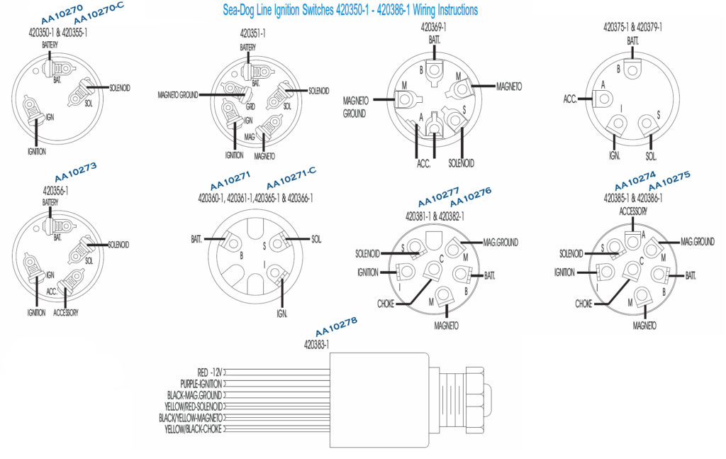
The ignition wiring diagrams show the various wires that are used to power the various components. In general, there are four different color-coded terminals for each component. Red is used for accessories while yellow is the battery, while green is the solenoid for starters. The “IGN” terminal lets you start your car, operate the wipers or other functions. The diagram shows the connections of the ACC- and ST terminals.
The terminal BAT is the connection for the battery. The battery is essential to allow the electrical system to begin. The switch will not turn on if there is no battery there. To locate your car’s battery, check your wiring diagram. The accessory terminals of your vehicle connect to the battery as well as the ignition switch. The BAT connector is connected to the battery.
Some ignition switches include an accessory position where users can alter their outputs as well as control them without having to turn on the ignition. Sometimes, customers would like the output of the auxiliary to be operated independently of the ignition. Use the secondary output by connecting it to an ACC terminal on the switch with the same colors. This convenience feature is great however there’s a distinction. Many ignition switches can be set to have an ACC position when the vehicle has been moved into the ACC position. They also will be in the START mode once the vehicle is entered the IGN position.
Gallery of 7 Pin Ignition Switch Wiring Diagram
Gallery of 7 Pin Ignition Switch Wiring Diagram


