Ignition Key Switch Wiring Diagram – We will first look at the various types and functions of the terminals on the ignition switches. These terminals are for the Ignition button, Coil and Accessory. After we’ve established the purpose of these terminals are We will then discover the various components of the Ignition Key Switch Wiring Diagram. In addition, we will discuss the functions of the Ignition switch and Coil. We’ll then turn our attention to the accessory terminals.
Terminals for ignition switches
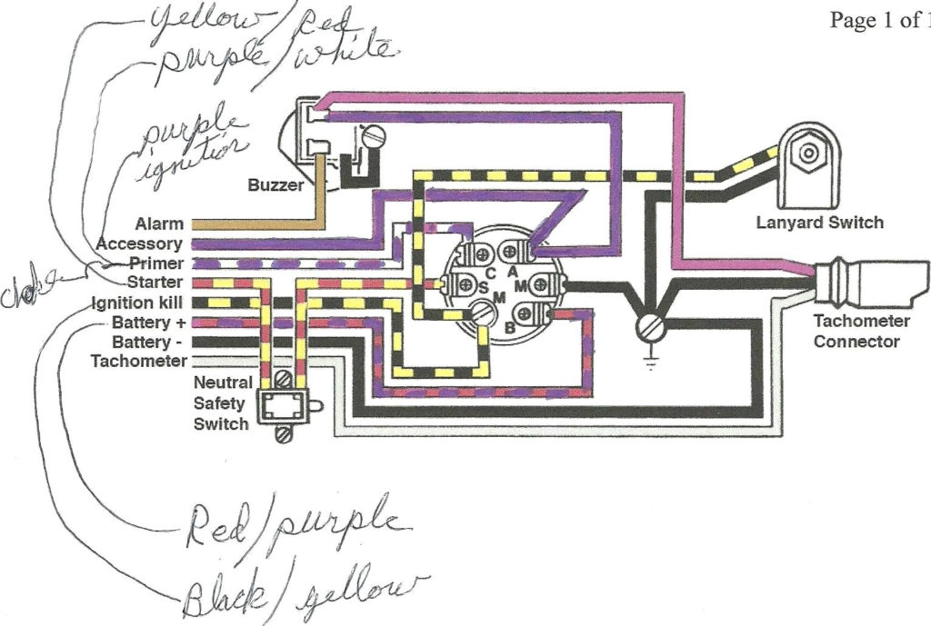
Three switches can be found in an ignition switch. Each of these switches is able to feed the battery’s voltage to various places. The choke is powered by the first switch. The second switch is responsible for the ON/OFF function of the ignition switch. Different manufacturers use different color codes for various conductors. This is explained in a different article. OMC follows this scheme. The connector permits the attachment of a speedometer the ignition switch.
While many ignition switch terminals might not be authentic, the numbering of each may not be in line with the diagram. Before you plug into the ignition switch be sure to test the continuity. This can be done using a cheap multimeter. After you’re happy with the continuity of the wires, then you’ll be able to connect the new connector. The wiring loom for the ignition switch factory-supplied will be different than the one you have in your car.
Understanding how ACC outputs are connected to the auxiliary outputs inside your car is vital. The ACC terminals as well as the IGN terminals are the standard connections for your ignition switch. The START and IGN connections are the main connections for radio and stereo. The ignition switch is accountable to turn the car’s engines on and off. Older cars have the ignition switch terminals labeled “ACC” or “ST” (for individual magnetowires).
Coil terminals
The terms used to define the type and model of an ignition coil is the primary thing. There are a variety of connections and terminals within an ignition wiring schematic that include two primary and two secondary. The coils come with a distinct operating voltage. The initial step in determining which type you’ve got is to check the voltage of S1 the primary terminal. S1 must also be subjected to resistance tests to determine if it are a Type A or B coil.
The chassis’ negative must be connected to the side of low-tension. This is also the ground in the wiring diagram for ignition. The high-tension side connects the spark plugs to a positive. To prevent noise the coil’s body metal must be connected to the chassis. This is not necessary to use electricity. The wiring diagram will illustrate the connection between the positive and negative coils. Sometimes, a malfunctioning ignition coil can be detected by a scan done at an auto repair shop.
The black-and-white-striped wire from the harness goes to the negative terminal. The negative terminal is served by the black trace that’s connected to the white wire. The black wire connects to the contact breaker. To verify the connection, make use of a paperclip or pencil to lift them out of the housing for the plug. Make sure that the terminals do not bend.
Accessory Terminals
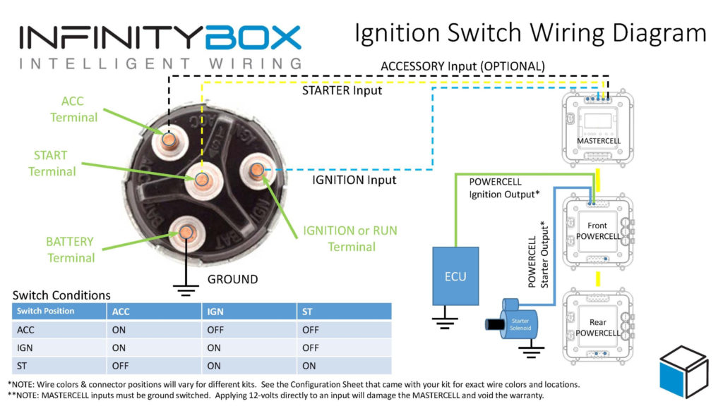
Diagrams of ignition wiring depict the wiring used in the vehicle’s power supply. Each component is equipped with four distinct color-coded connections. Red is used for accessories, yellow is for the battery, while green is the starter solenoid. The “IGN terminal allows you to start the car, control the wipers, and any other functions. The diagram illustrates the connection of the ACC- and ST terminals.
The terminal BAT is the connection for the battery. The battery is vital for the electrical system to begin. Additionally, the switch won’t start. You can refer to your wiring diagram if not sure where the batteries of your car are. The accessory terminals in your car are connected with the battery as well as the ignition button. The BAT connector is connected to the battery.
Some ignition switches come with an accessory position. This allows users to connect their outputs to another location without having to turn on the ignition. Some customers may prefer to utilize the auxiliary output separately from the ignition. The auxiliary output could be connected to connect the connector with the same colors as the ignition, and then connecting it to the ACC terminal of the switch. This is a convenient feature however it does have one key distinction. Most ignition switches will have an ACC position when the vehicle is in the ACC however, they’ll be at the START position if the vehicle is in IGN.
Gallery of Ignition Key Switch Wiring Diagram

Gallery of Ignition Key Switch Wiring Diagram


