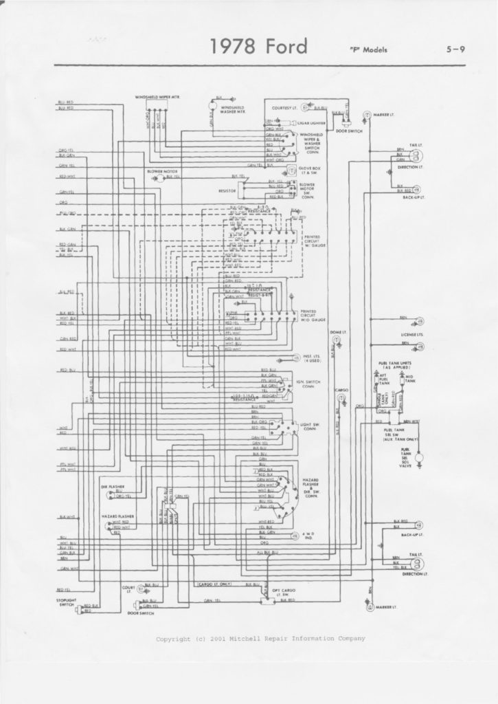
78 Ford Ignition Switch Wiring Diagram – The first step is to look at the different terminals that are used in the ignition switch. These terminals are for the Ignition button, Coil and Accessory. Once we’ve determined the function of the terminals we can determine the various components of the ignition wiring. Then, we will discuss the functions and the Coil. Following that, we’ll shift our attention to Accessory terminals.
Ignition switch terminals
Three switches are found on the ignition switch. Each of these switches is able to feed the battery’s voltage to various places. The ON/OFF state of the ignition switch is controlled by the second switch, which delivers power to the choke when it’s pulled. Different manufacturers have different colors for different conductors. This is explained in a different article. OMC uses this method. Connectors can be attached to the ignition switch to include a digital tachometer.
Even though some of the ignition switch terminals may not be authentic, the numbering of the terminals may not be in line with the diagram. To make sure that the wires are connected to the ignition switch it is recommended to check their continuity. A multimeter is a great tool to check the continuity. After you’re happy with the continuity of the wires install the new connector. The wiring loom for the ignition switch factory-supplied will be different than the one in your vehicle.
The first step is to understand the distinctions between ACC and secondary outputs. The ACC and IGN connectors are the standard connections for the ignition switch. Although the START, IGN, and ACC terminals are the primary connections for radios or stereo, the START/IGN connections are the main ones. The ignition switch regulates the engine in your car. The terminals of the ignition switch on older cars are identified with the initials “ACC” as well as “ST” (for the individual magneto wires).
Terminals for coil
Understanding the terminology utilized is the initial step to finding out the right kind of ignition coil you need. A basic ignition wiring layout will reveal a variety of terminals and connections. Each coil is operating at a certain voltage. The first step to determine the type you’re using is to examine the voltage of S1 or the primary terminal. To determine whether it’s an A, C or B coil you should also check the resistance of S1.
The low-tension end of the coil needs to be connected to the chassis the negative. This is also the ground in the diagram of ignition wiring. The high-tension supply provides positive directly to spark plugs. To prevent noise, the coil’s body metal must be connected with the chassis. It is not required to use electricity. The diagram of the ignition wiring will also show how to connect the positive coil’s terminals. Sometimes, a defective ignition coil can be detected by a scan done in an auto parts shop.
The black-and-white-striped wire from the harness goes to the negative terminal. The other white wire has a black color and goes to the terminal opposite. The black wire connects with the contact breaker. If you’re not sure about the connections between the twowires, use a paper clip to remove them from the housing of the plug. Be sure the terminals aren’t bent.
Accessory terminals
Diagrams of ignition wiring depict the wires used to supply power to different parts of the car. Typically there are four colored terminals for each part. The red color is used for accessories while yellow is the battery, while green is the solenoid for starters. The “IGN terminal” is used to power the wipers along with other operational features. The diagram illustrates how you can connect ACC or ST terminals and the rest.
The terminal BAT is the connection for the battery. The electrical system is not able to begin without the battery. Additionally the switch isn’t turned on. If you’re not sure of the location of your car’s battery situated, you can review the wiring diagram of your car to determine where it is. The accessory terminals on your vehicle connect to the battery and the ignition switch. The BAT Terminal is connected to the battery.
Some ignition switches offer an additional “accessory position” that allows users to modify their outputs independent of the ignition. Sometimes, users want to use an auxiliary output that is independent of the ignition. You can utilize the auxiliary input by connecting it to the ACC terminal. This is a great feature, however there’s one important difference. A majority of ignition switches feature an ACC position when the car is in ACC mode and a START position when it is in IGN.
Gallery of 78 Ford Ignition Switch Wiring Diagram
Gallery of 78 Ford Ignition Switch Wiring Diagram


