Crane Hi 6 Ignition Wiring Diagram – Let’s start by looking at the various types terminals found on the ignition switch. These terminals are for the Ignition button, Coil and Accessory. After we’ve identified what these terminals do, we will identify the different parts in the ignition wiring. We’ll also go over the roles of the Ignition switch, as well as the Coil. After that we will proceed to the Accessory Terminals.
The terminals of the ignition switch
There are three switches on an ignition switch, which provide the battery’s voltage to various destinations. The first is used to turn on the choke by pushing it, and another switch controls the ON/OFF setting. Each manufacturer has its own color-coding system, which we’ll go over in a separate article. OMC uses this approach. A tachometer adapter is installed on the ignition switch to allow the installation of a Tachometer.
While most ignition switch terminals aren’t authentic, the numbering of each might not be consistent with the diagram. Before plugging into the ignition switch, make sure to check the continuity. A multimeter is a good tool to test the continuity. Once you’ve verified the integrity of the wires you can then install the connector. If your car is equipped with an original ignition switch supplied by the factory (or a wiring loom) The wiring loom might differ from the one in the car.
For connecting the ACC outputs to the auxiliary outputs on your car, you’ll need to first understand how these two connections work. The ACC, IGN and START terminals are your default connections to the ignition switch. They are also the main connections to the radio and stereo. The ignition switch controls the car’s engine. Older cars have the ignition switch terminals marked “ACC” or “ST” (for individual magnetowires).
Terminals for coil
To figure out the type of ignition coil you need to know the step is to know the terminology. An ignition wiring diagram will display a range of terminals and connections comprising two primary and two secondaries. The operating voltage of each coil is different. It is crucial to test the voltage at the S1 (primary terminal). S1 should also undergo resistance testing to determine if it’s a Type A or B coil.
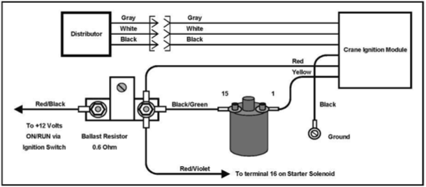
The coil with low tension must be connected at the chassis’s plus. This is what is known as the ground for the wiring for ignition. The high-tension part is a positive connection to the sparkplugs. To prevent noise, the coil’s metal body is required to be connected to the chassis. But, it’s not necessary to electrically connect. The wiring diagram of the ignition will show you how to connect the terminals of either the positive or negative coils. You may find an issue with your ignition coil which can be identified by scanning it in an auto parts store.
The black-and-white-striped wire from the harness goes to the negative terminal. The positive terminal is connected to the white wire and an trace of black. The black wire connects to the contact breaker. If you’re unsure of the connections of the two, try using the clip of a paperclip to remove them from the housing of the plug. You should also check to ensure that the terminals aren’t bent.
Accessory terminals
The diagrams for ignition wiring depict the wires used in the power supply of the vehicle. There are usually four different colored terminals for each component. The accessories are colored red and the battery yellow the starter solenoid is green. The “IGN” terminal is used to turn on the car, turn on the wipers, and other features. The diagram shows how you can connect the ACC and ST terminals to the rest of the components.
The terminal referred to as BAT is where the battery is connected. The electrical system won’t start if the battery isn’t connected. A dead battery can make the switch not turn on. You may refer to the wiring diagram if you’re not sure where the batteries of your car are located. The ignition switch and the battery are connected through the accessory terminals. The BAT terminal is connected with the battery.
Some ignition switches feature the “accessory” setting that allows users to regulate their outputs without needing to turn on the ignition. Sometimes, customers would like the auxiliary output to be used separately from the ignition. Use the additional output by connecting the connector to the ACC terminal on the switch with the same colors. This is a useful option, but there’s an important distinction. Most ignition switches are configured to display an ACC status when the vehicle is in the ACC or START positions.
Gallery of Crane Hi 6 Ignition Wiring Diagram
Gallery of Crane Hi 6 Ignition Wiring Diagram


