8n Ignition Switch Wiring Diagram – The first step is to take a look at the different types of terminals on the ignition switch. These terminals are used for the Ignition button, Coil and Accessory. After we’ve identified the purpose of these terminals, we will be able to identify the various parts of the ignition wiring. We’ll also discuss the roles of both the Ignition Switch and Coil. After that, we will turn our attention towards the accessories terminals.
Terminals for the ignition switch
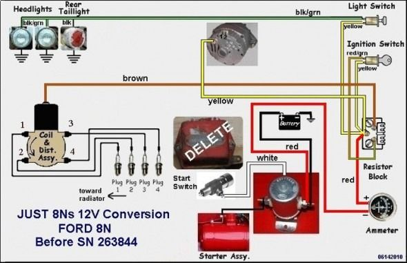
The ignition switch consists of three different switches. These are responsible for supplying the battery’s energy to various locations. The first switch supplies the choke with power when it is pushed. The third is the position of the ignition switch’s ON/OFF. Different manufacturers have different color-coding systems that correspond to the conductors. OMC follows this system. The adapter is attached to the ignition switch, allowing the installation of an tachometer.
While the majority of the ignition switch terminals are not authentic, the numbering of each one may not be in line with the diagram. To make sure that the wires are properly plugged in to the switch, you should check their continuity. A cheap multimeter can help you do this. When you’re satisfied with the integrity of your wires, you will be able to install the new connector. If your car has an original factory-supplied ignition switch (or wiring loom) the wiring loom may differ from that in your vehicle.
To connect the ACC outputs to the auxiliary outputs on your vehicle, you have to understand the way these two connections function. The ACC and IGN connectors are the default connections of the ignition switch. Although the START, IGN, and ACC terminals are the primary connections to the radio or stereo, the START/IGN terminals are the main ones. The ignition switch is the one that turns the car’s engine on and off. The terminals for the ignition switch on older cars are labeled with the initials “ACC” as well as “ST” (for the individual magneto wires).
Terminals for coil
The first step in determining the type of ignition coil is to comprehend the terms that is used. The basic ignition wiring diagram depicts various connections and terminals. There are two primary and one secondary. The operating voltage of each coil differs. Therefore, it is crucial to test the voltage at S1 (primary terminal). S1 must also be inspected for resistance in order to identify if it’s an A, Type B or an A coil.
The negative of the chassis must be connected to the side of low-tension. It is also the ground in an ignition wiring diagram. The high-tension supply delivers the spark plugs with positive electricity directly. The aluminum body of the coil has to be connected to the chassis for suppression however it’s not electrically required. The ignition wiring diagram will also show the connection of the positive coil terminals. It is possible to find an ignition coil problem which can be identified by scanning it at an auto parts store.
The black-and-white-striped wire from the harness goes to the negative terminal. The white wire is black-colored and goes to the terminal opposite. The black wire is connected to the contactbreaker. If you’re not certain about the connection between the two, try using the clip of a paperclip to remove them from the plug housing. It’s also crucial to ensure that the terminals aren’t bent.
Accessory Terminals
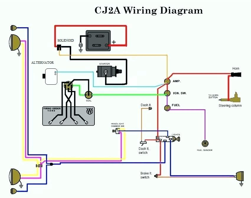
Diagrams of ignition wiring depict the wires that supply power to different parts of the car. Each part has four distinct connections that are color coded. To identify accessories, red is for starter solenoid, yellow is for battery, and blue for accessory. The “IGN terminal” is used to power the wipers and other operating features. This diagram shows how to connect ACC and ST terminals with the other components.
The terminal referred to as BAT is the location where the battery is. The electrical system won’t start in the event that the battery isn’t connected. The switch also won’t turn on without the battery. You can view your wiring diagram to determine the location of your car’s batteries. placed. The ignition switch is connected to the battery of your car. The BAT Terminal is connected to the Battery.
Some ignition switches feature an additional “accessory” location, which allows users can manage their outputs with no ignition. Users may wish to utilize the auxiliary output separately from the ignition. To use the auxiliary output, wire the connector with identical colors to the ignition and connect it to the ACC terminal on the switch. Although this is a great feature, there’s one thing you need to know. Most ignition switches are set to have an ACC position when the vehicle is in the ACC position, whereas they’re set to the START position when the car is in the IGN position.
Gallery of 8n Ignition Switch Wiring Diagram
Gallery of 8n Ignition Switch Wiring Diagram


