Yamaha Ignition Wiring Diagram – First, we will look at the different types of terminals found in the ignition switch. These terminals are for the Ignition button, Coil and Accessory. Once we’ve established the purpose of these terminals, we will be able to identify the various parts of the ignition wiring. We’ll also be discussing the roles of the Ignition switch, as well as the Coil. The next step is to focus on the accessory terminals.
Terminals for ignition switches
An ignition switch contains three different switches that direct the battery’s power to various locations. The first switch provides power to the choke whenever it is pushed. The third is the ignition switch’s ON/OFF position. Different manufacturers have various color codes for the various conductors. This is described in a different article. OMC employs this system. The ignition switch comes with a connector for adding an timer.
Although many ignition switch terminals do not appear in their original configuration The numbering might not match the diagram. To make sure that your wires are correctly plugged in to the switch, it is recommended to check their continuity. This can be done with a simple multimeter. When you’re happy with the quality of the connection, you can place the new connector. If your vehicle has an original ignition switch supplied by the factory (or an electrical loom) The wiring loom will differ from the one in your car.
Knowing how the ACC outputs connect to the auxiliary outputs in your vehicle is crucial. The ACC and IGN connectors are the standard connections of your ignition switch. While the START, IGN, and ACC terminals are the primary connections for the radio or stereo, the START/IGN terminals are the most important ones. The ignition switch turns the engine of your car ON and OFF. Older cars are identified by the alphabets “ACC”, “ST”, (for individual magneto cables) at the ignition switch terminals.
Terminals for coil
The terminology used to determine the model and type of the ignition coil is the primary thing. There are a variety of connections and terminals in an ignition wiring schematic that include two primary and two secondary. The coils come with a distinct operating voltage. The first step to determine which one you’ve got is to check the voltage on S1, the primary terminal. S1 must also go through resistance tests to determine if it are an A or B coil.
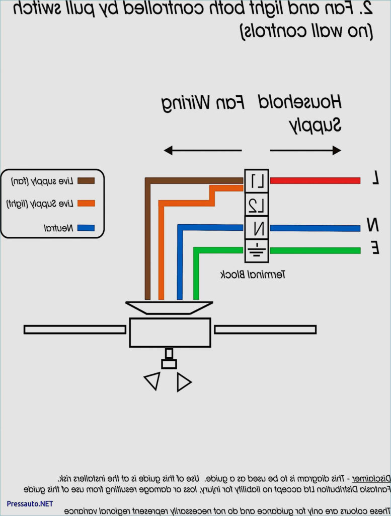
The negative of the chassis must be connected to the low-tension side. This is exactly what you can see in the diagram of wiring. The high-tension side connects the spark plugs to a positive. The body of the coil has to be connected to the chassis to prevent it from being smothered however it isn’t electrically essential. The diagram of the ignition wiring will also show the connection of the positive coil terminals. Sometimes, a damaged ignition coil is identified with a scan in an auto parts shop.
The black-and-white-striped wire from the harness goes to the negative terminal. The other white wire has a black color and connects to the terminal opposite. The black wire connects with the contact breaker. To check the connection, employ a paperclip, or a pencil to remove them of the plug housing. You should also check to see that the terminals aren’t bent.
Accessory terminals
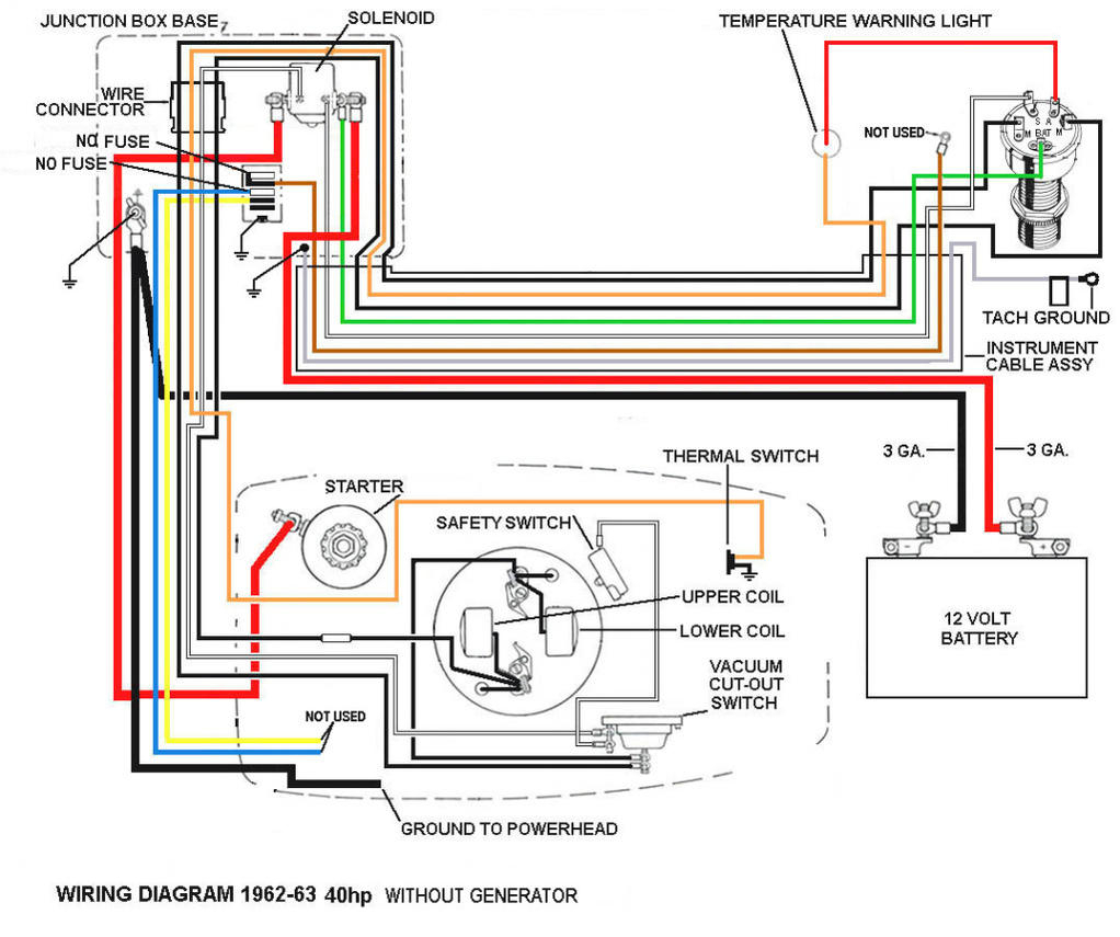
Diagrams of ignition wiring depict the wiring used in the vehicle’s power supply. There are typically four colors of terminals connected to each part. The red symbol represents accessories, yellow for the battery and green for the starter solenoid. The “IGN” terminal is used to start the car, operating the wipers and other functions. This diagram shows how to connect ACC and ST terminals to the other components.
The battery is attached to the terminal named BAT. The electrical system can’t be started without the battery. Also, the switch won’t start without the battery. If you’re not sure the exact location where the battery in your car is situated, you can look at your wiring diagram to see how to locate it. The ignition switch and the battery are connected through the accessory terminals. The BAT connector connects to your battery.
Some ignition switches feature an independent “accessory” position, where users can control their outputs with no ignition. Sometimes, customers would like an auxiliary output that can be operated independently of the ignition. In order for the auxiliary output be used, wire the connector with the same shade as the ignition. Then connect it with the ACC end of the switch. Although this is a useful feature, there is one significant difference. Most ignition switches will be in an ACC position if the car is in ACC however they will be at the START position if the vehicle is in IGN.
Gallery of Yamaha Ignition Wiring Diagram
Gallery of Yamaha Ignition Wiring Diagram


