91 S10 Ignition Wiring Diagram – Let’s begin by looking at the different types terminals found on an ignition switch. These terminals serve for the Ignition button, Coil and Accessory. After we’ve established the purpose of these terminals are We will then identify the different parts of the 91 S10 Ignition Wiring Diagram. We’ll also be discussing the function of the Ignition switch, as well as the Coil. Then, we’ll turn our attention to Accessory terminals.
Terminals for ignition switch
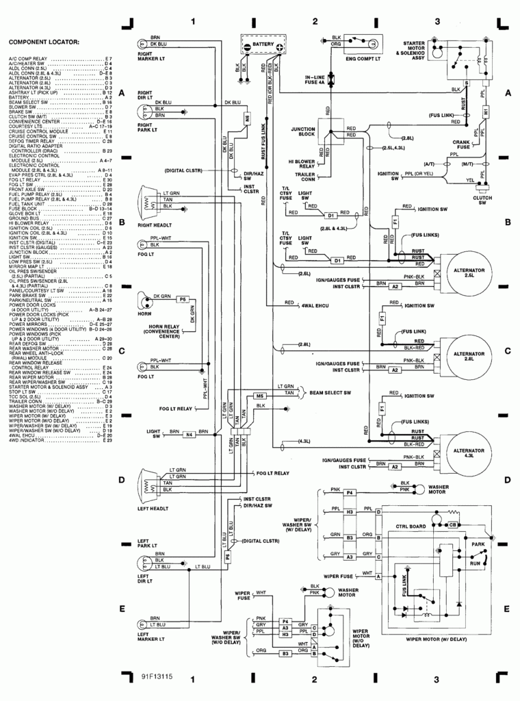
An ignition switch has three switches. They feed the voltage of the battery to many different locations. The ON/OFF setting of the ignition switch is controlled by the second switch, which delivers the choke with power when it’s pushed. Different manufacturers have their own color-coding system for different conductors that is described in a separate article. OMC utilizes the same system. The connector allows for the attachment of a speedometer to the ignition switch.
Even though some of the ignition switch terminals could not be original, the numbering of each may not be in line with the diagram. Check the continuity of all wires to ensure they are correctly plugged into the ignition switches. This can be done using a simple multimeter. When you’re happy with the connection, you can place the new connector. If your car has an ignition switch installed the wiring diagram will differ.
Before you can connect the ACC outputs to the auxiliary outputs of your car It is essential to understand the basics of these connections. The ACC and IGN connectors are the standard connections of your ignition switch. While the START, IGN, and ACC terminals are the primary connections for radios or stereo, the START/IGN terminals are the primary ones. The ignition switch is the one that controls the engine of your car. On older vehicles the terminals of the ignition switch are marked with the initials “ACC”, and “ST” (for distinct magnet wires).
Terminals for coil
Understanding the terms that is used is the initial step towards finding out the right kind of ignition coil you need. A simple diagram of the wiring will show a variety of connections and terminals, which include two primary terminals and two secondary. The voltage that operates on each coil is different. This is why it is crucial to test the voltage at S1 (primary terminal). S1 must also be inspected for resistance in order to identify if the coil is a Type B, B, or an A coil.
The chassis’ negative should be connected to connect the coil’s low-tension end. This is what’s called the ground on the ignition wiring diagram. The high-tension component supplies positively directly to the spark plugs. It is essential for suppression purposes that the coil’s metallic body be connected to its chassis, however, it is not necessary. There are also connections of the negative and positive coil terminals on the diagram of the ignition wiring. Sometimes, an inspection at an auto part store can diagnose a malfunctioning ignition wire.
The black-and-white-striped wire from the harness goes to the negative terminal. The white wire is the other one. It is black with a trace, and it goes to the positive terminal. The black wire is connected to the contact breaker. To check the connection, use a paperclip or a pencil to pull them out of the housing for the plug. It is also important to ensure that the terminals aren’t bent.
Accessory Terminals

Diagrams of ignition wiring illustrate the wires used to provide power to various components of the vehicle. There are typically four color-coded terminals to each component. To identify accessories, red stands for starter solenoid, blue for battery, and blue for accessories. The “IGN terminal” is used to power the wipers and other operating functions. The diagram shows the connection between the ACC- and ST terminals.
The terminal BAT holds the battery. Without the battery the electrical system will not get started. The switch will not turn on if there is no battery there. The wiring diagram will inform you where to find the battery in your car. Your car’s accessory terminals are connected to the ignition switch and the battery. The BAT terminal is connected with the battery.
Some ignition switches include an accessory position where users can adjust their outputs and manage them without the need to use the ignition. Customers may want to utilize the auxiliary output separately from the ignition. In order to use the auxiliary output, wire the connector with the same colors as ignition connecting it to the ACC terminal on the switch. While this is an excellent feature, there is one significant difference. Most ignition switches are configured to show an ACC status when the car’s at either the ACC or START position.
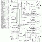
Gallery of 91 S10 Ignition Wiring Diagram
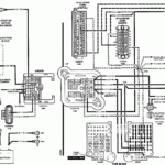
Gallery of 91 S10 Ignition Wiring Diagram


