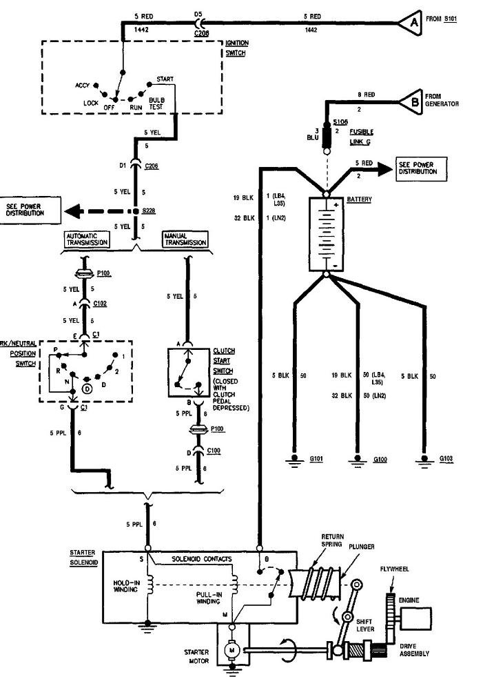
95 S10 Ignition Switch Wiring Diagram – We will first look at the different types of terminals that are found in the ignition switch. These include the terminals that are for the Ignition switch, Coil, and Accessory. Once we know the purpose of each kind of terminal, it is possible to identify the various components of the ignition wiring. Then, we will discuss the functions as well as the Coil. Then we’ll discuss the Accessory Terminals.
Terminals for ignition switches
There are three switches in the ignition switch, and they feed the battery’s voltage to a variety of places. The first is used to turn on the choke through pushing it, while the second is for the ON/OFF setting. Each manufacturer has their own color-coding system, which we’ll discuss in a subsequent article. OMC uses this system. A connector is also included inside the ignition switch for connecting an Tachometer.
Even though the majority of ignition switch terminals don’t come in original form, the numbering may not be in line with the diagram. You should first check the electrical continuity to ensure that they are plugged into the correct ignition switch. You can do this with an inexpensive multimeter. When you’re satisfied with the continuity of the wires, then you’ll be able install the new connector. The wiring loom used in a factory-supplied ignition system switch differs.
Before you can connect the ACC outputs to the auxiliary outputs of your car It is essential to know the fundamentals of these connections. The ACC terminals and IGN terminals are the primary connections to the ignition switch. The START and IGN connections are the primary connections for stereo and radio. The ignition switch is the engine’s switch to turn off or on. Older cars are identified with the letters “ACC”, “ST”, (for individual magneto cables) at the ignition switch terminals.
Terminals for coil
The language used to decide the kind and model of an ignition coil is the primary thing. An understanding of the basic wiring diagram for ignition will provide you with a range of terminals and connections. Each coil is operating at a certain voltage. The first step to determine the type you have is to check the voltage of S1 or the primary terminal. S1 must be tested for resistance in order to determine if the coil belongs to Type A, B, or C.
The low-tension coil side must be connected at the chassis’s less. This is the ground on the diagram of ignition wiring. The high-tension side supplies positive direct to the sparkplugs. To reduce the noise the coil’s body metal must be connected to the chassis. This is not necessary to use electricity. The wiring diagram for the ignition will demonstrate how to connect the two terminals of the negative or positive coils. Sometimes, an inspection at an auto parts store could diagnose a malfunctioning ignition wire.
The black-and-white-striped wire from the harness goes to the negative terminal. The white wire is black and goes to the negative terminal. The contact breaker is linked to the black wire. It is possible to check the connections with a pencil to pull the wires out from the housing. It’s also crucial to make sure that the terminals aren’t bent.
Accessory Terminals
Ignition wiring diagrams show the various wires used to power the car’s various parts. There are generally four colored terminals for each component. For accessories, red stands for starter solenoid, yellow for battery and blue for accessory. The “IGN” terminal allows you to start the car, control the wipers, or any other features that operate. The diagram illustrates how you can connect ACC or ST terminals and the rest.
The terminal BAT connects the battery to the charger. Without the battery, the electrical system does not start. A dead battery can cause the switch to not turn on. If you don’t know the location of your car’s battery situated, review your wiring diagram to see where it is. The ignition switch and the battery are connected through the accessory terminals. The BAT terminal connects to the battery.
Some ignition switches include an accessory position where users can modify their outputs and control them without having to turn on the ignition. Sometimes, customers want to utilize an additional output that is not connected to the ignition. You can use the auxiliary output by connecting it to an ACC terminal on the switch using the same colors. This is a great feature, however there’s one important distinction. Most ignition switches will have an ACC position if the car is in ACC however they’ll be in the START position when the car is in IGN.
Gallery of 95 S10 Ignition Switch Wiring Diagram
Gallery of 95 S10 Ignition Switch Wiring Diagram


