John Deere 2010 Ignition Switch Wiring Diagram – Let’s begin by looking at different types terminals found in an ignition switch. They are terminals that are used for Coil, Ignition Switch, and Accessory. Once we understand the function of each type of terminal, it is possible to identify the parts of the ignition wiring. In addition, we will discuss the roles of both the Ignition Switch and Coil. Following that, we’ll shift our attention to the Accessory terminals.
The terminals of the ignition switch
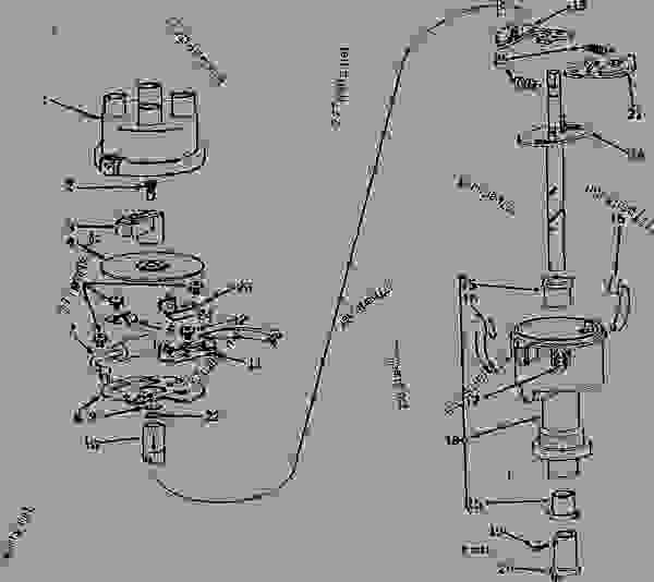
The ignition switch has three switches. They transmit the battery’s voltage to different places. The first switch is the one that supplies power to the choke, while the second toggles the state of the switch. Different manufacturers have different colour-coding systems that correspond to the conductors. OMC employs this system. The ignition switch also includes a connector for adding the timer.
Although the majority of ignition switch terminals don’t carry an original number, they may have a different one. The first step is to check the continuity of all the wires to ensure that they are properly connected to the ignition switches. A cheap multimeter can aid in this. After you’re happy with the continuity of the wires install the new connector. The wiring loom used in an ignition system switch that is supplied by the manufacturer is distinct.
Understanding how ACC outputs connect to the other outputs of your car is essential. The ACC terminals as well as the IGN terminals serve as the standard connections for the ignition switch. The START and IGN connections are the primary connections for radio and stereo. The ignition switch switches the car’s engine on and off. On older cars the ignition switch’s terminals are identified with the alphabets “ACC” as well as “ST” (for the individual magnetic wires).
Terminals for coil
The language used to decide the kind and model of an ignition coil is the primary thing. A basic ignition wiring layout will provide you with a range of connections and terminals. Each coil is equipped with a distinct operating voltage. To determine the type of coil you own first, you need to check the voltage at S1, which is the primary terminal. S1 must be checked for resistance to determine if the coil is Type A, B, or C.
The low-tension side of the coil should be connected to the chassis’ negative. This is the ground in the wiring diagram for ignition. The high-tension side delivers the positive power directly to the spark plugs. The metal body of the coil needs to be connected to the chassis for suppression purposes but is not electrically essential. It is also possible to see the connections of the positive and negative coil’s terminals on an diagram of the ignition wiring. Sometimes, a visit to an auto part store can detect a defective ignition wire.
The black-and-white-striped wire from the harness goes to the negative terminal. The white wire is black-colored and connects to the terminal opposite. The black wire connects to the contactbreaker. To confirm the connections, employ a paperclip, or a pencil to pull them out of the plug housing. Make sure that the connectors aren’t bent.
Accessory terminals
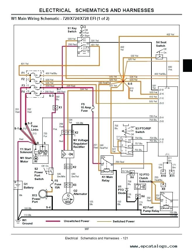
Ignition wiring diagrams show the different wires that are utilized to power the vehicle’s various components. Each part has four distinct colored connections. Red stands for accessories, yellow represents the battery, and green for the solenoid for starters. The “IGN” terminal is used to start the vehicle, controlling the wipers and various other functions. The diagram shows how to connect the ACC and ST terminals to the rest of the components.
The terminal called BAT is the location where the battery is. The electrical system will not start without the battery. Furthermore, the switch won’t begin to turn on. If you’re not sure of where your car’s battery is situated, you can examine the wiring diagram of your car to determine the best way to find it. The accessory terminals in your car are connected to the battery and ignition button. The BAT connector is connected to the battery.
Certain ignition switches have an additional position. This lets users connect their outputs to another location without the ignition. Sometimes, customers would like the auxiliary output to be used separately from the ignition. To make use of the auxiliary output, wire the connector in the same colors as the ignition, connecting it to the ACC terminal on the switch. While this is a convenient feature, there’s one significant difference. Some ignition switches are set to have an ACC position once the car has moved into the ACC position. They also will be in the START mode after the vehicle has been entered the IGN position.
Gallery of John Deere 2010 Ignition Switch Wiring Diagram
Gallery of John Deere 2010 Ignition Switch Wiring Diagram


