93 Mustang Ignition Wiring Diagram – Let’s first examine the various terminals on the ignition switch. These are terminals for Coil, Ignition Switch, and Accessory. Once we know the purpose of these terminals are used for, we will proceed to identify the different parts of the 93 Mustang Ignition Wiring Diagram. We’ll also discuss the functions of both the Ignition Switch and the Coil. Following that, we’ll shift our attention to Accessory terminals.
Terminals for the ignition switch
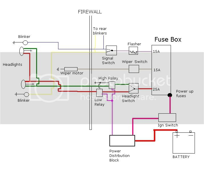
An ignition switch contains three separate switches that feed the battery’s current to various destinations. The first switch supplies power to the choke, while the second switch controls the on/off state of the switch. Each manufacturer has its own color-coding system, which we’ll discuss in a subsequent article. OMC uses this method. The adapter is attached to the ignition switch that allows the addition of the tonometer.
Even though some of the ignition switch terminals may not be original, the numbers of each one might not be in line with the diagram. Check the continuity of each wire to make sure they’re properly connected to the ignition switches. This can be done using a cheap multimeter. Once you’re satisfied with the quality of the connection, you can place the new connector. The wiring loom for an ignition switch that’s factory-supplied will be different than the one in your car.
Before connecting the ACC outputs to the auxiliary outputs of your car It is essential to know the fundamentals of these connections. The ACC terminals as well as the IGN terminals serve as the default connections to your ignition switch. The START and IGN connections are the main connections for stereo and radio. The ignition switch turns the engine of your car ON and off. The terminals for the ignition switch on older cars are labeled with the initials “ACC” as well as “ST” (for each magneto wires).
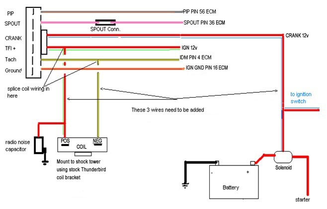
Terminals for coil
The first step to determine the kind of ignition coil is to understand the terms that is used. You will see several connections and terminals on the basic wiring diagram for ignition which includes two primary as well as two secondary. Each coil is operating at a certain voltage. The first step to determine which kind you have is to check the voltage of S1 or the primary terminal. S1 must also be inspected for resistance to determine if the coil is a Type B, B or A coil.
The chassis’ negative must be connected to the side of low-tension. This is the wiring diagram you will find in the diagram of wiring. The high-tension side supplies the positive power directly to the spark plugs. The coil’s aluminum body needs to be connected to the chassis to prevent it from being smothered but isn’t required. The wiring diagram for ignition will also show how to connect the positive coil terminals. In some cases it is recommended to conduct a scan at your local auto parts shop will help identify malfunctioning ignition coils.
The black-and-white-striped wire from the harness goes to the negative terminal. The terminal that is negative is served by the trace in black that’s connected to the white wire. The black wire is connected to the contact breaker. If you’re not sure about the connections of the twowires, use the clip of a paperclip to remove them from the housing of the plug. Be sure that the terminals aren’t bent.
Accessory terminals
Diagrams of ignition wiring show the different wires that are used to power the car’s various parts. Typically there are four color-coded terminals for each component. For accessories, red stands for starter solenoid, yellow is for battery and blue for accessory. The “IGN” terminal can be used to start the vehicle and control the wipers, as well as other operating features. The diagram below illustrates how to connect the ACC terminal as well as the ST terminals to other components.
The terminal BAT is where the battery is. The electrical system cannot start without the battery. A dead battery could cause the switch to not come on. You may refer to the wiring diagram if you’re unsure where your car’s batteries are. Your car’s accessory terminals connect to the ignition switch as well as the battery. The BAT terminal is connected with the battery.
Some ignition switches feature the “accessory” position that allows users to control their outputs , without needing to utilize the ignition. Some customers want the output of the auxiliary to be used independently from the ignition. You can use the auxiliary output by connecting it to the ACC terminal on your switch with the same colors. Although this is a useful feature, there’s one crucial distinction. Most ignition switches come with an ACC position when the car is in the ACC mode and a START mode when you are in IGN.
Gallery of 93 Mustang Ignition Wiring Diagram
Gallery of 93 Mustang Ignition Wiring Diagram


