Wiring Diagram For Revtech Motorcycle Ignition – First, we will examine the different types of terminals for the ignition switch. These terminals serve for the Ignition button, Coil and Accessory. Once we’ve established the purpose of the terminals we can determine the various components of the ignition wiring. In addition, we will discuss the function of the Ignition switch and Coil. Following that, we’ll shift our attention to Accessory terminals.
Terminals for ignition switch
An ignition switch contains three different switches that direct the battery’s power to various destinations. The first switch provides power to the choke whenever it is pushed. The second is the ignition switch’s ON/OFF position. Different manufacturers use their own color-coding systems for the various conductors, that is described in a separate article. OMC follows this method. Connectors can be attached to the ignition switch to add the digital tachometer.
Although the majority of ignition switch terminals are duplicated, the numbers may not be consistent with the diagram. Before plugging into the ignition switch, be sure to test the continuity. A multimeter is a good tool to test the continuity. After you’re sure that all wires are in good continuity then you can connect the new connector. If your car is equipped with an original ignition switch supplied by the factory (or a wiring loom) The wiring loom might differ from the one in your car.
To connect the ACC outputs to the auxiliary outputs on your car, you need to first understand how these two connections work. The ACC and IGN terminals are the default connections on the ignition switch. the START and IGN terminals are the primary connections to the stereo and radio. The ignition switch is the one that turns the engine of your car on and off. The terminals on older cars ignition switches are identified with “ACC” and ST (for specific magneto wires).
Terminals for coil
To identify the kind of ignition coil, the first step is to understand the terminology. A basic ignition wiring layout will reveal a variety of terminals and connections. You need to determine the type of coil that you own by examining the voltage at the primary terminal, called S1. You should also examine S1 for resistance to determine whether it is a Type A, B, or C coil.
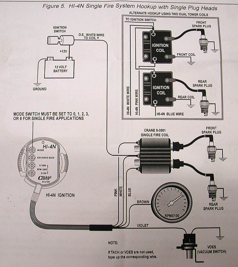
The negative end of the chassis end should be connected to connect the coil’s low-tension end. This is also the ground on the wiring diagram for ignition. The high-tension part is a positive connection to the sparkplugs. For suppression purposes the coil’s metal body is required to be connected to the chassis. This is not necessary to use electricity. A wiring diagram can illustrate the connection between the positive and negative coil terminals. You may find an issue with your ignition coil that is easily identified by looking it up at an auto parts store.
The black-and-white-striped wire from the harness goes to the negative terminal. The positive terminal also receives the second white wire, which has a black trace. The contact breaker is attached to the black wire. To verify the wires’ connections, use a paperclip to lift them out of the housing. Be sure that the terminals aren’t bent.
Accessory terminals
Diagrams of ignition wiring depict the wires used to supply power to different parts of the vehicle. Each component is equipped with four distinct colored connections. The accessories are colored red, the battery is yellow and the starter solenoid green. The “IGN terminal is used to start the car, operating the wipers and various other functions. The diagram shows how to connect ACC or ST terminals and the rest.
The terminal BAT is the connector for the battery. The electrical system can’t be started without the battery. The switch will not turn on if there is no battery present. To find your car’s battery look over your wiring diagram. The ignition switch and the battery are connected via accessory terminals. The BAT Terminal is connected to the Battery.
Some ignition switches come with an accessory position. This lets users access their outputs from another location without the ignition. Customers sometimes want the auxiliary output to be operated independently of the ignition. You can utilize the additional input by connecting it to the ACC terminal. While this is an excellent feature, there’s one important difference. Many ignition switches have an ACC position when the car is in ACC mode and a START position when it is in IGN.
Gallery of Wiring Diagram For Revtech Motorcycle Ignition

Gallery of Wiring Diagram For Revtech Motorcycle Ignition


