New Holland Ignition Switch Wiring Diagram – We’ll begin by looking at the various types of terminals in an ignition switch. They are terminals for Coil, Ignition Switch, and Accessory. Once we know the purpose of these terminals are then we can identify the different parts of the New Holland Ignition Switch Wiring Diagram. Then, we will discuss the functions as well as the Coil. After that, we’ll turn our attention to Accessory terminals.
Terminals for ignition switches

Three switches are located on an ignition switch. Each of the three switches is able to feed the battery’s voltage to several different places. The first switch is the one that supplies power to the choke and the third switch toggles the state of the switch. Every manufacturer has its individual color-coding system that we’ll go over in a separate article. OMC utilizes this method. Connectors can be connected to the ignition switch to connect the digital tachometer.
Although the majority of ignition switch terminals can be duplicated, the numbers might not be in line with the diagram. Examine the integrity of the wires first to ensure that they are correctly plugged in the ignition switch. A simple multimeter will aid in this. When you are happy with the continuity of the wires, you can connect the new connector. The wiring loom used in an ignition system switch that is supplied by the manufacturer is different.
It is important to know the differences between ACC and auxiliary outputs. The ACC and IGN connectors are the default connections for the ignition switch. While the START, IGN, and ACC terminals are the primary connections for radios or stereo, the START/IGN terminals are the most important ones. The ignition switch is responsible to turn the car’s engines on and off. Older cars have the ignition switch’s terminals that are labeled “ACC” or “ST” (for individual magnetowires).
Terminals for coil
The terminology used to determine the kind and model of the ignition coil is the primary thing. There are a variety of connections and terminals on a basic ignition wiring schematic, including two primary, and two secondary. Each coil is equipped with a distinct operating voltage. To determine which type of coil you own first, you need to test the voltage at S1, the primary terminal. To determine whether it’s an A, C or B coil you should also check the resistance of S1.
The low-tension side of the coil should be connected to the chassis the negative. This is the ground on the wiring diagram for ignition. The high-tension side delivers positive directly to the spark plugs. The aluminum body of the coil has to be linked to the chassis to prevent it from being smothered but isn’t required. It is also possible to see the connections between the positive and negative coil’s terminals on an ignition wiring diagram. Sometimes, an inspection at an auto parts store could identify a problem with the ignition wire.
The black-and-white-striped wire from the harness goes to the negative terminal. The terminal for the negative is served by the black trace attached to the white wire. The black wire connects to the contactbreaker. You can examine the connections with a pencil to take the wires out from the housing. It is also important to make sure that the terminals do not bend.
Accessory terminals

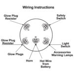
Ignition wiring diagrams depict the various wires that are used for powering the different components. There are generally four colored terminals for each component. Red stands for accessories, yellow for the battery, and green for the starter solenoid. The “IGN terminal” is used to provide power to the wipers and other operating functions. The below diagram illustrates how to connect the ACC terminal as well as the ST terminals to various components.
The terminal BAT connects the battery to the charger. Without the battery the electrical system will not start. The switch won’t be able to turn on if the battery isn’t present. To find the battery in your car look over your wiring diagram. The accessory terminals of your car are connected to the battery and the ignition switch. The BAT terminal is connected to the battery.
Some ignition switches have the “accessory” position that allows users to control their outputs without needing to turn on the ignition. Some customers might want to use the auxiliary output separately from the ignition. You can utilize the secondary input by connecting the connector to the ACC terminal. This convenience feature is great however, there’s one differentiator. Most ignition switches are designed to show an ACC status when the car is in either the ACC or START positions.
Gallery of New Holland Ignition Switch Wiring Diagram
Gallery of New Holland Ignition Switch Wiring Diagram


