98 Honda Civic Ignition Wiring Diagram – We will first take a look at the different kinds of terminals on the ignition switch. They include terminals that are used for Coil, Ignition Switch, and Accessory. Once we understand the function of each terminal, it is possible to identify the various components of the ignition wiring. We’ll also go over what functions are available for the Ignition switch and the Coil. After that, we will focus on the accessory terminals.
Terminals for ignition switches
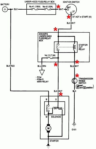
There are three switches on an ignition switch that feed the battery’s voltage to various places. The first switch supplies the choke with power when it is pushed. The second is the ignition switch’s ON/OFF position. Different manufacturers use different color-coding methods to identify different conductors. This will be covered in another article. OMC utilizes this approach. The connector allows for the attachment of a speedometer the ignition switch.
Although the majority of ignition switch terminals don’t carry an original number, they may have a different number. First, check the continuity of each wire to ensure they are correctly plugged into the ignition switches. This can be done with a simple multimeter. After you’re satisfied with the continuity it’s time to connect the new connector. The wiring loom in an ignition system switch that is supplied by the manufacturer differs.
Before connecting the ACC outputs to your car’s auxiliary outputs, it is important to know the fundamentals of these connections. The ACC terminals and IGN terminals are the default connections to your ignition switch. The START and IGN connections are the most important connections for stereo and radio. The ignition switch is accountable for turning the car’s engine on and off. Older cars have the ignition switch’s terminals that are labeled “ACC” or “ST” (for individual magnetowires).
Terminals for coil
The first step to determine the kind of ignition coil is to know the terms used. In a basic diagram of the wiring for ignition you’ll see a number of different connections and terminals, such as two primary and two secondary. You must determine the type of coil you are using by testing the voltage at the primary terminal S1. Also, you should test S1 for resistance in order to determine if it’s an A B, C, or coil.
The chassis’ negative needs to be connected to the low-tension side. This is the ground of the wiring for ignition. The high-tension part is a positive connection to the sparkplugs. The coil’s aluminum body needs to be connected to the chassis for suppression, but it isn’t electrically required. You will also see the connections between the negative and positive coil terminals on the diagram of the ignition wiring. Sometimes, a visit to an auto part store can identify a problem with the ignition wire.
The black-and-white-striped wire from the harness goes to the negative terminal. The terminal that is negative is served by the black trace joined to the white wire. The black wire is connected to the contact breaker. To verify the connections between the two wires use a paperclip and lift them off the housing. Be sure the terminals do not bend.
Accessory Terminals
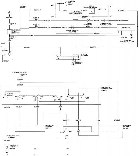
Diagrams of ignition wiring illustrate the wires that power various parts of the vehicle. Each component is equipped with four distinct colored connections. The red color is for accessories, yellow the battery, and green for the starter solenoid. The “IGN” terminal lets you start the car, control the wipers, and any other functions. The diagram illustrates how you can connect ACC or ST terminals and the rest.
The terminal BAT is the connector for the battery. The electrical system will not start without the battery. Furthermore the switch won’t come on. The wiring diagram will show you the location of the battery of your car. The accessory terminals of your car connect to the battery and the ignition switch. The BAT connector is connected to your battery.
Some ignition switches feature an “accessory” setting that permits users to control their outputs , without having to use the ignition. Sometimes, users want to utilize an additional output that is not connected to the ignition. The auxiliary output can be utilized by wiring the connector in the same color as your ignition, and then attaching it to the ACC terminal of the switch. This is a great convenience feature however there’s a differentiator. Most ignition switches come with the ACC position when the car is in ACC mode and a START mode when you are in IGN.
Gallery of 98 Honda Civic Ignition Wiring Diagram
Gallery of 98 Honda Civic Ignition Wiring Diagram


