Ford Ignition Coil Wiring Diagram – First, let’s take a look at the different types of terminals on the ignition switch. These include the terminals that are for the Ignition switch, Coil, and Accessory. Once we know what these kinds of terminals are for We will then identify the different parts of the Ford Ignition Coil Wiring Diagram. We will also discuss what functions are available for the Ignition switch, as well as the Coil. The next step is to focus to the accessory terminals.
The ignition switch’s terminals
The ignition switch is comprised of three switches that supply the battery’s current to different destinations. The first switch powers the choke. The third switch regulates the ON/OFF function of the ignition switch. Different manufacturers use different colour-coding systems that correspond to the conductors. OMC uses this system. The adapter is attached to the ignition switch that allows the installation of the tachometer.
While most ignition switch terminals can be duplicated, the numbers may not be in line with the diagram. To make sure that your wires are correctly plugged in to the ignition switch, it is recommended to check their continuity. This can be done using a simple multimeter. Once you are satisfied that the wires are running in good harmony and you are able to connect the new connector. The wiring loom in the ignition system switch supplied by the manufacturer differs.
The first step is to understand the distinctions between the ACC and auxiliary outputs. The ACC/IGN terminals function as the default connection on the ignition switch. The START/IGN terminals connect to the stereo or radio. The ignition switch turns the engine of your car ON and OFF. Older cars are equipped with ignition switch terminals labeled “ACC” or “ST” (for individual magnetowires).
Coil terminals
The first step in determining the type of ignition coil is to know the terminology employed. An ignition wiring diagram will display a range of terminals and connections which include two primary terminals and two secondaries. Each coil comes with its own operating voltage. To determine which type of coil you’ve got the first step is to check the voltage at the S1 primary terminal. You should also examine S1 for resistance to identify if it’s an A, B, or C coil.
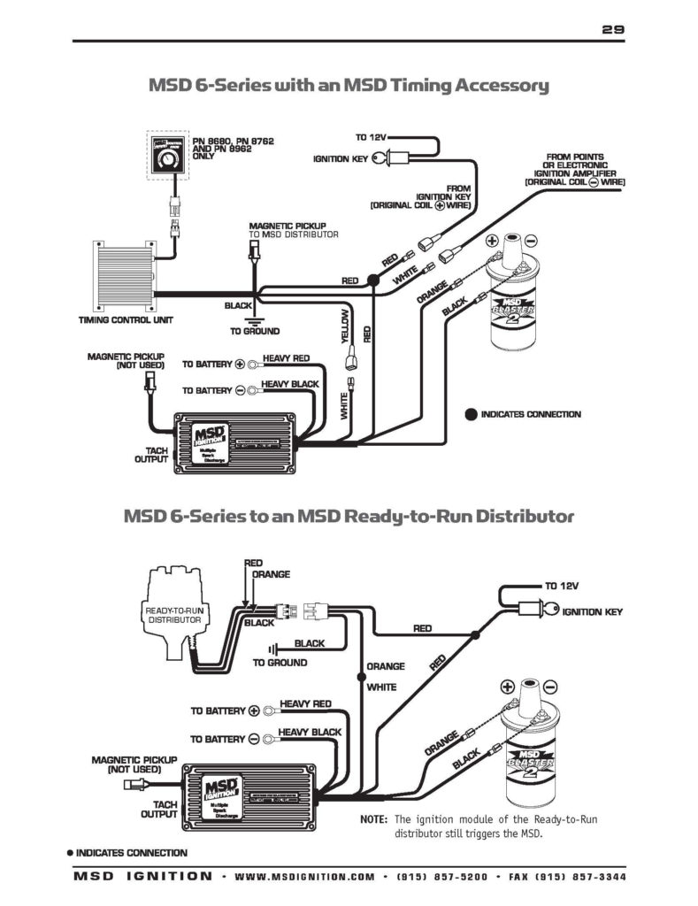
The lower-tension side of the coil needs to be connected to the chassis’ negative. This is the ground in the ignition wiring diagram. The high-tension part provides positive direct to the sparkplugs. The aluminum body of the coil needs to be connected to the chassis for suppression but isn’t required. The wiring diagram of the ignition will show you how to connect the two terminals of the positive or negative coils. Sometimes, a damaged ignition coil can be identified by a scan done at an auto parts shop.
The black-and-white-striped wire from the harness goes to the negative terminal. The other white wire is black and goes to the terminal opposite. The black wire goes to the contact breaker. If you’re not sure about the connection between the twowires, use a paper clip to remove them from the housing of the plug. It is also important to make sure that the connections aren’t bent.
Accessory terminals
Ignition wiring diagrams depict the different wires used to power the various components. In general there are four colored terminals for each part. Red refers to accessories, yellow the battery, and green is the starter solenoid. The “IGN terminal allows you to start the car, manage the wipers, and any other operation features. The diagram shows how to connect ACC or ST terminals and the rest.
The terminal BAT connects the battery to the charger. The electrical system can’t start without the battery. The switch also won’t start without the battery. If you’re not sure of the location of your car’s battery situated, you can review the wiring diagram of your car to determine where it is. The ignition switch and the battery are connected by the accessory terminals. The BAT terminal is connected to the battery.
Some ignition switches offer an additional “accessory position” that allows users to adjust their outputs independently of the ignition. Some customers might want to utilize the auxiliary input independently of the ignition. It is possible to use the auxiliary input by connecting it to the ACC terminal. While this is a convenient feature, there is one crucial distinction. Most ignition switches are configured to have an ACC status when the vehicle is in the ACC or START position.
Gallery of Ford Ignition Coil Wiring Diagram
Gallery of Ford Ignition Coil Wiring Diagram


