Aircraft Ignition Switch Wiring Diagram – The first step is to examine the different types of terminals that are used on the ignition switch. These terminals are used for the Ignition button, Coil and Accessory. When we have a clear understanding of the purpose of each terminal, it is possible to identify the various components of the ignition wiring. We’ll also go over the functions for the Ignition switch, as well as the Coil. After that, we will focus on the accessory terminals.
The ignition switch’s terminals
Three switches are found in an ignition switch. Each of the three switches is able to feed the battery’s voltage to various locations. The first switch powers the choke. The second switch controls the ON/OFF of the ignition switch. Different manufacturers have different color-coding schemes to identify different conductors. This will be covered in a separate article. OMC uses this system. A tachometer adapter is installed on the ignition switch, allowing for the addition of a Tachometer.
While most ignition switch terminals aren’t original, the numbering for each may not match the diagram. The first step is to check the continuity of all the wires to ensure that they are properly plugged into the ignition switches. This can be checked using a cheap multimeter. Once you’re satisfied about the continuity of the wires, then you’ll be able to install the new connector. If you are using an ignition switch that is supplied by the manufacturer the wiring loom will be different from that used in your vehicle.
You must first understand how the ACC outputs and auxiliary outputs function to connect them. The ACC/IGN terminals function as the default connections on the ignition switch. The START/IGN connections connect to the stereo or radio. The ignition switch is accountable for turning the car’s engine on and off. The terminals of the ignition switch on older cars are identified with the letters “ACC” as well as “ST” (for each magneto wires).
Terminals for coil
Understanding the terminology that is used is the initial step to determining the kind of ignition coil to choose. In a simple diagram of the wiring for ignition, you will see several different connections and terminals, which include two primary and two secondary. The operating voltage of every coil is different. It is essential to first check the voltage at S1 (primary terminal). S1 should also be tested for resistance in order to identify if it’s an A, Type B or A coil.
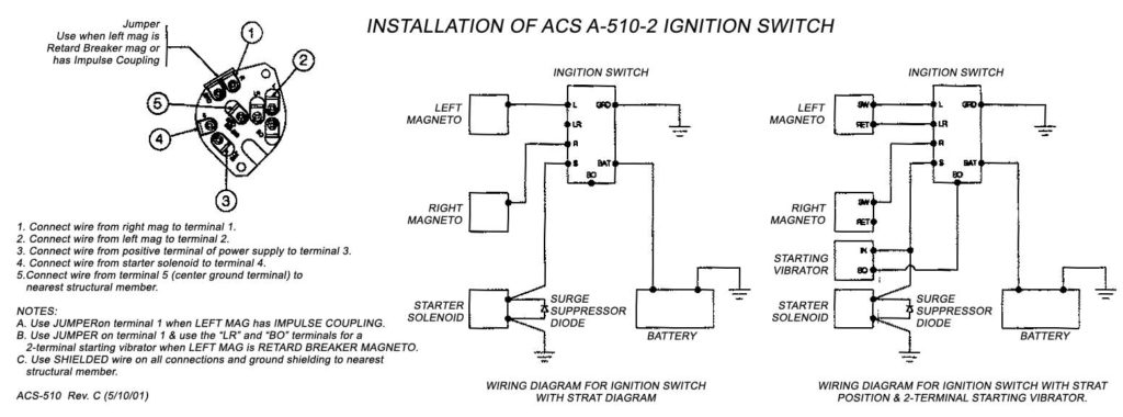
The lower-tension side of the coil must be connected to the chassis’ negative. This is the wiring diagram you will see on the wiring diagram. The high tension side provides positive power directly to the spark plugs. The metal body of the coil needs to be connected to the chassis for suppression purposes however it isn’t electrically required. The wiring diagram for the ignition will show you how to connect the two terminals of the negative or positive coils. Sometimes, a malfunctioning ignition coil is identified with a scan at an auto repair shop.
The black-and-white-striped wire from the harness goes to the negative terminal. Positive terminal gets the second white wire, which is black in its trace. The contact breaker is linked to the black wire. If you’re unsure of the connection between the two, try using an old paper clip to take them from the housing of the plug. It’s also essential to ensure that the terminals do not bend.
Accessory terminals
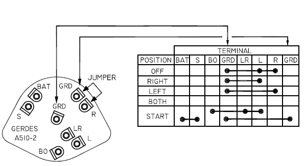
The ignition wiring diagrams show the various wires utilized to power the different components. Each component is equipped with four distinct colored connections. The accessories are red and the battery yellow, and the starter solenoid green. The “IGN terminal” is used to power the wipers as well as other operating functions. The below diagram shows how to connect the ACC terminal as well as the ST terminals to various components.
The terminal BAT is the connection for the battery. The battery is vital to allow the electrical system to begin. In addition the switch isn’t turned on. To find your car’s battery look over your wiring diagram. The accessory terminals in your car connect to the ignition switch as well as the battery. The BAT terminal connects to the battery.
Some ignition switches have the “accessory” setting that allows users to regulate their outputs without having to use the ignition. Sometimes, users want to make use of an additional output that is not connected to the ignition. To use the auxiliary output, wire the connector with identical colors to the ignition and connect it to the ACC terminal on the switch. This is an excellent option, but there’s one important difference. Most ignition switches come with the ACC position when your car is in the ACC mode, and a START position when it is in IGN.
Gallery of Aircraft Ignition Switch Wiring Diagram
Gallery of Aircraft Ignition Switch Wiring Diagram


