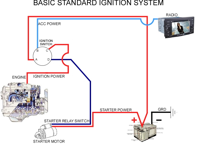
Basic Ignition System Wiring Diagram – First, we will examine the different types of terminals for the ignition switch. These terminals are for the Ignition button, Coil and Accessory. Once we have identified the purpose of these terminals and what they do, we can then determine the various components in the ignition wiring. In addition, we will discuss the functions of both the Ignition Switch and the Coil. After that, we will focus on the accessories terminals.
Terminals for ignition switch
There are three different switches in an ignition switch, which feed the battery’s voltage to various places. The ON/OFF setting of the ignition switch is controlled by the first switch, which supplies power to the choke when it is pushed. Different manufacturers have different color-coding schemes to identify different conductors. We will cover this in a different article. OMC utilizes this method. The ignition switch comes with an adapter for the addition of the Tachometer.
While most ignition switch terminals are duplicated, the number may not match the diagram. First, check the continuity of each wire to ensure that they are properly plugged into the ignition switches. A simple multimeter will aid in this. After you’re satisfied with the connection, you can place the new connector. If your car has an ignition switch that is installed the wiring diagram will differ.
First, understand the differences between ACC and secondary outputs. The ACC and IGN connectors are the standard connections of your ignition switch. The START, IGN, and ACC terminals are the main connections for the radio or stereo, the START/IGN connections are the main ones. The ignition switch operates the engine’s on/off button. The ignition switch terminals on older cars are identified with the letters “ACC” as well as “ST” (for each magneto wires).
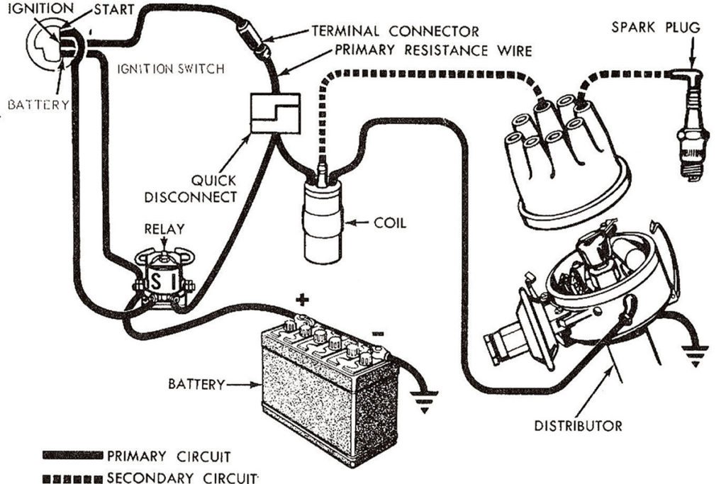
Terminals for coil
The terms used to define the kind and model of an ignition coil is the primary thing. An ignition wiring diagram will display a range of terminals and connections, comprising two primary and two secondaries. The coils have a specific operating voltage. The first step to determine which one you have will involve testing the voltage of S1 the primary terminal. S1 should also be tested for resistance to determine if it’s an A, Type B, or A coil.
The negative end of the chassis should be connected to connect to the coil’s lower-tension end. This is also the ground on the ignition wiring diagram. The high-tension side supplies the spark plugs with positive. To reduce the noise the coil’s metal body is required to be connected to the chassis. It’s not necessary to use electricity. A wiring diagram can also show the connection between the positive and negative coils. In certain instances, a scan at your local auto parts store will be able to diagnose defective ignition coils.
The black-and-white-striped wire from the harness goes to the negative terminal. The positive terminal also gets the white wire that includes a black trace. The black wire is connected to the contact breaker. You can take the black wire from the housing of the plug with a paper clip in case you are uncertain about the connection. Also, make sure to verify that the connections have not been bent.
Accessory Terminals
Diagrams of ignition wiring show the various wires utilized to power the vehicle’s various parts. In general there are four color-coded terminals for each component. Red is used to indicate accessories, yellow to the battery, and green the starter solenoid. The “IGN” terminal allows you to start the car, manage the wipers or other functions. The diagram illustrates how to connect ACC or ST terminals, and other.
The battery is attached to the terminal whose name is BAT. The battery is necessary to allow the electrical system to get started. In addition, the switch will not start. You can view the wiring diagram of your car to see where the batteries of your car are located. The ignition switch is connected to the car’s battery. The BAT Terminal is connected to the Battery.
Some ignition switches feature an additional “accessory” position, where users can control their outputs without the ignition. Some customers might want to use the auxiliary output separately from the ignition. To use the auxiliary output, wire the connector in the same colors as ignition and connect it to the ACC terminal on the switch. This feature of convenience is fantastic however there’s a difference. Most ignition switches are configured to be in an ACC position when the car is in the ACC position, but they’re in the START position when the vehicle is in the IGN position.
Gallery of Basic Ignition System Wiring Diagram
Gallery of Basic Ignition System Wiring Diagram


