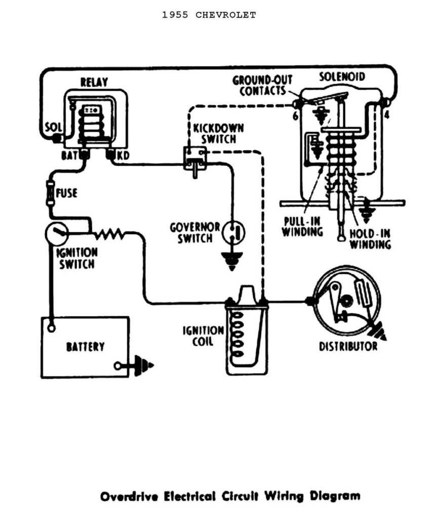
Basic Points Ignition Wiring Diagram – In the beginning, we’ll examine the various types of terminals that are found in the ignition switch. These include the terminals for the Ignition switch, Coil, and Accessory. After we’ve identified the terminals used then we can recognize the various parts of the Basic Points Ignition Wiring Diagram. We’ll also discuss the functions as well as the Coil. Then, we’ll talk about the roles of the Ignition switch and Coil.
Ignition switch terminals
Three switches are located in an ignition switch. Each of these three switches is able to feed the battery’s voltage to a variety of destinations. The choke is powered by the first switch. The second switch controls the ON/OFF of the ignition switch. Different manufacturers use different color-coding methods to identify different conductors. We will cover this in a separate article. OMC uses the same method. There is a connector in the ignition switch to allow attaching a tachometer.
Although the majority of ignition switch terminals are duplicated, the numbers may not be consistent with the diagram. Before plugging in the ignition switch, ensure that you check the continuity. This can be done with a simple multimeter. After you’re sure that all wires are in good order and you are able to connect the new connector. If your vehicle is equipped with an ignition switch that is installed, the wiring diagram will differ.
Before connecting the ACC outputs to your car’s auxiliary outputs, it is important to know the fundamentals of these connections. The ACC and IGN connectors are the standard connections of your ignition switch. Although the START, IGN, and ACC terminals are primary connections for radios or stereo, the START/IGN terminals are the most important ones. The ignition switch turns the car’s engine on and off. The terminals of older vehicles’ ignition switches are labeled by “ACC” as well as ST (for the individual magneto wires).
Terminals for Coil
To determine the type of ignition coil, the first step is to learn the definition of. An understanding of the basic wiring diagram for ignition will provide you with a range of connections and terminals. Each coil operates at a specific voltage. The first step in determining which type you have is to check the voltage on S1, or the primary terminal. S1 must also be inspected for resistance in order to identify if it’s an A, Type B or A coil.
The low-tension end of the coil needs to be connected to the chassis’ negative. It is also the ground in the diagram of ignition wiring. The high tension side supplies positively directly to the spark plugs. The aluminum body of the coil needs to be connected to the chassis for suppression, but it isn’t electrically required. The ignition wiring diagram will also reveal the connection of the negative and positive coil terminals. In some cases you’ll discover that an ignition coil that is malfunctioning is identified by scans in an auto parts store.
The black-and-white-striped wire from the harness goes to the negative terminal. The white wire is the other one. It is black with a trace on it, and connects to the positive terminal. The black wire connects to the contact breaker. To test the wires’ connections use a paperclip to lift them out of the housing. It is also important to ensure that the terminals are not bent.
Accessory terminals
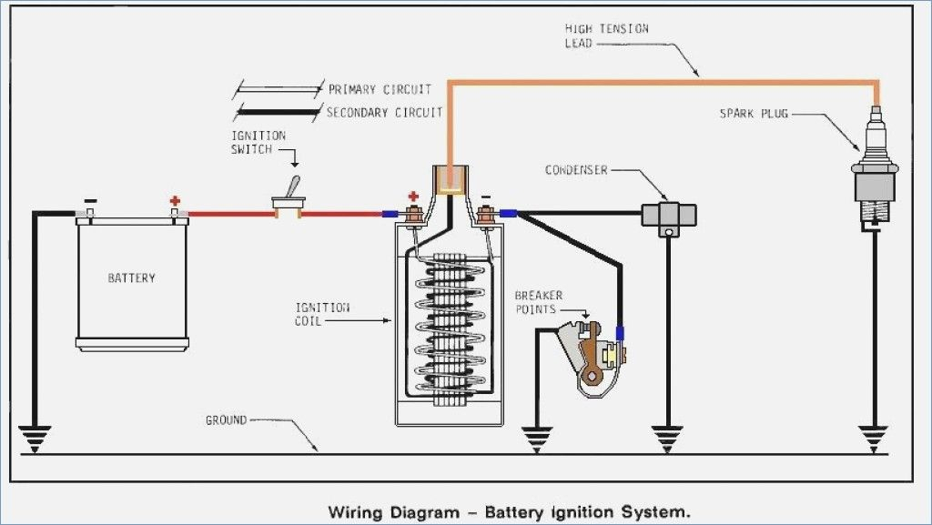
The ignition wiring diagrams illustrate the various wires utilized to power the vehicle’s various parts. Typically, there are four different color-coded terminals for each component. The red symbol represents accessories, yellow is for the battery, and green for the starter solenoid. The “IGN terminal is used to start the car, controlling the wipers, and for other functions. The following diagram shows how to connect both the ACC terminal and ST terminals to various components.
The terminal BAT is where the battery is. The electrical system can’t start without the battery. A dead battery could cause the switch to not come on. You can refer to your wiring diagram if unsure where your car’s batteries are. The accessory terminals in your car connect to the ignition switch, as well as the battery. The BAT connector connects to your battery.
Some ignition switches come with an independent “accessory” location, which allows users can manage their outputs without using the ignition. Some customers may prefer to utilize the auxiliary output independently of the ignition. The auxiliary output is connected to connect the connector with the same colors as your ignition, and then attaching it to the ACC terminal of the switch. This is an excellent feature, but there is an important difference. Most ignition switches are configured to show an ACC status when the car is at either the ACC or START position.
Gallery of Basic Points Ignition Wiring Diagram
Gallery of Basic Points Ignition Wiring Diagram


