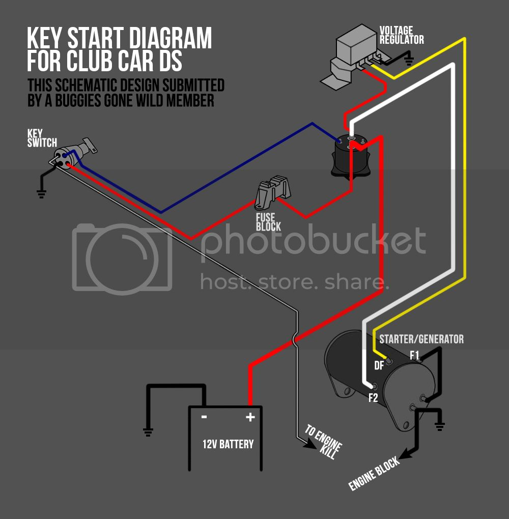
Club Car Ignition Switch Wiring Diagram – Let’s begin by looking at the different kinds of terminals that are found on the ignition switch. They are terminals that are used for Coil, Ignition Switch, and Accessory. Once we know the purpose of these terminals are for, we will proceed to identify the different parts of the Club Car Ignition Switch Wiring Diagram. In addition, we will discuss the roles of the Ignition switch and Coil. Then, we’ll focus to the accessory terminals.
Terminals for the ignition switch
The ignition switch has three switches. They supply the battery’s voltage to many different locations. The first switch powers the choke. The third switch regulates the ON/OFF switch of the ignition switch. Different manufacturers have their own color-coding system for the various conductors, that is described in a separate article. OMC follows the same system. A tachometer adapter is installed on the ignition switch that allows for the addition of an tachometer.
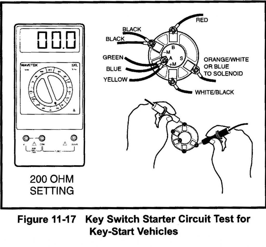
While most ignition switch terminals are not original, the numbering for each may not match the diagram. It is important to first verify the electrical continuity to determine if they’re plugged into the correct ignition switch. A multimeter is a great instrument to verify the continuity. After you’ve confirmed the continuity of the wires you can install the connector. If you have an ignition switch that is supplied by the manufacturer the wiring loom may be distinct from the one that is you have in your car.
Knowing how the ACC outputs are connected to the other outputs inside your car is vital. The ACC/IGN terminals act as the default connection on the ignition switch. The START/IGN terminals connect to the stereo or radio. The ignition switch is the engine’s on/off button. The terminals on older cars ignition switches are marked by “ACC” and ST (for individual magneto wires).
Terminals for coil
To identify the kind of ignition coil, the initial step is to know the terms. You will see several connections and terminals in a basic ignition wiring schematic which includes two primary as well as two secondary. You must determine the kind of coil you own by examining the voltage at the primary terminal, S1. To determine if the coil is a Type A, C or B coil you must also test S1’s resistance.
The low-tension side of the coil needs to be connected to the chassis”negative. This is the wiring diagram you will see on the wiring diagram. The high tension part supplies positively directly to the spark plugs. It is necessary for the purpose of suppression that the body of the coil’s metal be connected to its chassis however it isn’t essential. There are also connections between the positive and the negative coil terminals on the diagram of the ignition wiring. Sometimes, a damaged ignition coil can be detected through a scan performed at an auto parts shop.
The black-and-white-striped wire from the harness goes to the negative terminal. The other white wire has a black trace, and it goes to the positive terminal. The black wire connects to the contact breaker. If you’re unsure of the connections of both, you can use a paper clip to remove them from the plug housing. It’s also essential to make sure the terminals do not bend.
Accessory terminals
The diagrams for ignition wiring depict the wiring used in the power supply of the vehicle. Each component is equipped with four distinct colored connections. The red symbol represents accessories, yellow for the battery, and green for the starter solenoid. The “IGN terminal is used to start the car, operating the wipers and various other functions. The diagram shows the connection of the ACCand ST terminals.
The terminal BAT connects the battery to the charger. The electrical system will not start if the battery isn’t connected. Furthermore, the switch doesn’t turn on. It is possible to refer to your wiring diagram if unsure where your car’s batteries are. Your car’s accessory terminals connect to the ignition switch, as well as the battery. The BAT terminal connects to the battery.
Some ignition switches feature an additional “accessory” position, where users can control their outputs with no ignition. Some customers want an auxiliary output that can be used independently from the ignition. To make use of the auxiliary output, wire the connector using the same colors as the ignition connecting it to the ACC terminal on the switch. While this is a convenient feature, there’s one important difference. The majority of ignition switches are set up to show an ACC status when the vehicle is at the ACC or START positions.
Gallery of Club Car Ignition Switch Wiring Diagram
Gallery of Club Car Ignition Switch Wiring Diagram


