Bobcat 753 Ignition Switch Wiring Diagram – First, we will look at the different types of terminals found in the ignition switch. These are terminals for Coil, Ignition Switch, and Accessory. After we’ve identified the purpose of these terminals, we will be able to recognize the various parts of the ignition wiring. We will also cover the functions of both the Ignition Switch and Coil. Next, we’ll discuss the functions of the ignition switch and Coil.
The terminals are for ignition switches.
Three switches can be found in an ignition switch. Each of the three switches feeds the battery’s voltage to a variety of locations. The first switch supplies power to the choke when it is pushed. The third is the position of the ignition switch’s ON/OFF. Different manufacturers have distinct colors-coding systems to match the conductors. OMC follows this approach. A connector can be added to the ignition switch to add an electronic Tachometer.
While most ignition switch terminals may not be original, the numbering for each might not be consistent with the diagram. Before plugging into the ignition switch make sure to check the continuity. A multimeter is a good tool to test the continuity. Once you’re satisfied about the integrity of your wires, you will be able install the new connector. If your vehicle has an original ignition switch supplied by the factory (or wiring loom) the wiring loom might differ from that in your car.
You must first understand the ways in which the ACC outputs and the auxiliary outputs function to join them. The ACC/IGN terminals function as the default connections for the ignition switch. The START/IGN connections connect to the stereo or radio. The ignition switch acts as the engine’s off/on button. On older vehicles, the ignition switch terminals are marked with the alphabets “ACC” as well as “ST” (for individual magnet wires).
Terminals for coil
The terms used to define the type and model of an ignition coil is the most important thing. There are a variety of connections and terminals within the basic wiring diagram for ignition, including two primary, and two secondary. Each coil has a specific operating voltage. To determine the type of coil you have the first step is to test the voltage at S1, the primary terminal. S1 should also be tested for resistance in order to identify if the coil is a Type B, B, or A coil.
The negative end of the chassis should be connected to connect the coil’s low-tension end. This is what’s called the ground on the wiring diagram for ignition. The high-tension side connects the spark plugs to a positive. To reduce the noise the body of the coil is required to be connected to the chassis. However, it is not necessary to connect the coil electrically. The diagram of the ignition wiring will also outline how to connect the positive coil’s terminals. Sometimes, a check at an auto part store can identify a problem with the ignition wire.
The black-and-white-striped wire from the harness goes to the negative terminal. The negative terminal is served by the black trace that’s connected to the white wire. The black wire connects to the contact breaker. You can take the black wire from the housing of the plug with a paper clip in case you are uncertain about the connections. Make sure that the connectors do not bend.
Accessory terminals
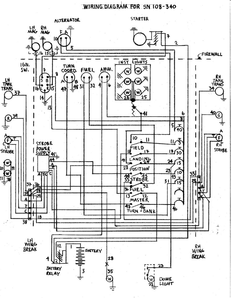
The ignition wiring diagrams show the different wires used to power the various components. There are usually four colored terminus lines for each component. The red color represents accessories, yellow represents the battery and green for the solenoid for starters. The “IGN terminal” is used to provide power to the wipers as well as other operating functions. This diagram demonstrates how to connect ACC and ST terminals to the rest of the components.
The terminal BAT holds the battery. The electrical system can’t be started without the battery. A dead battery can make the switch not come on. A wiring diagram can tell the location of the battery in your car. The ignition switch is connected to the car’s battery. The BAT connector is connected to the battery.
Certain ignition switches have an accessory position where users can alter their outputs and manage them without needing to use the ignition. Customers sometimes want the output of the auxiliary to be used independently from the ignition. You can use the auxiliary output by connecting it to an ACC terminal on the switch that has the same color. While this is an excellent feature, there’s one thing you need to know. A majority of ignition switches feature an ACC position when your car is in the ACC mode, and a START position when it is in IGN.
Gallery of Bobcat 753 Ignition Switch Wiring Diagram
Gallery of Bobcat 753 Ignition Switch Wiring Diagram


