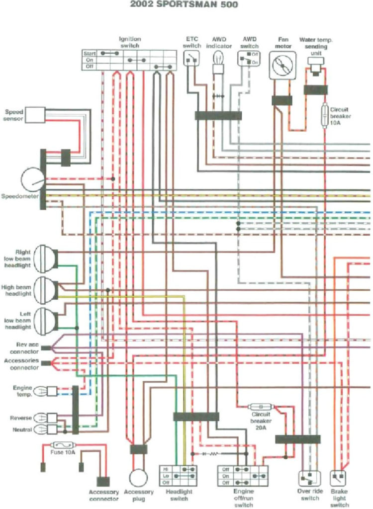
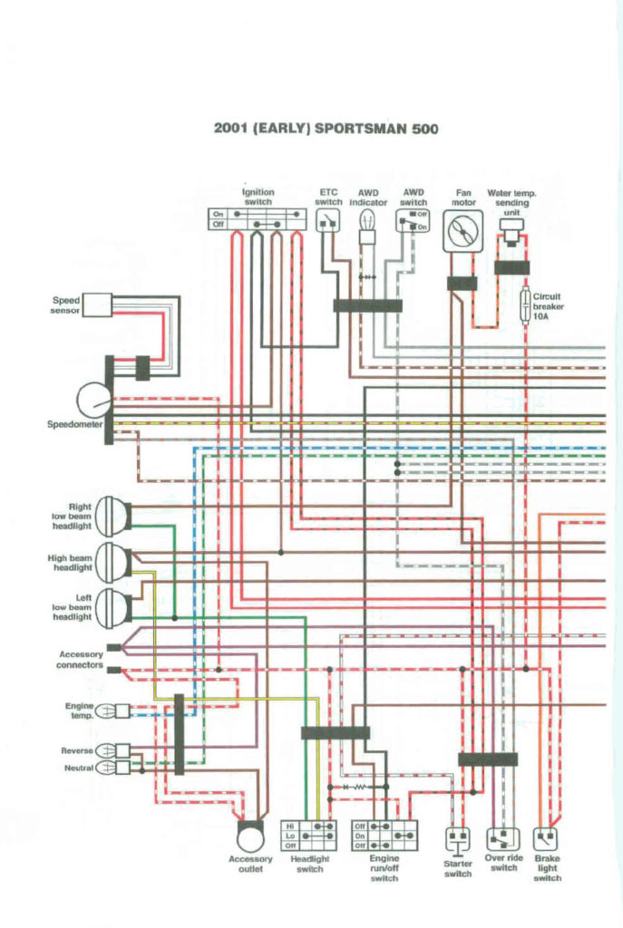
Polaris Sportsman 500 Ignition Switch Wiring Diagram – Let’s begin by examining the different types and functions of the terminals that are found in the ignition switches. They are the terminals used for Coil, Ignition Switch, and Accessory. Once we know the purpose of each type of terminal, we are able to determine the components of the ignition wiring. We’ll also be discussing the roles of the Ignition switch, as well as the Coil. The next step is to focus on the accessory terminals.
Terminals for ignition switch
An ignition switch is comprised of three switches. They feed the voltage of the battery to different locations. The first switch is the one that supplies power to the choke while the second toggles the state of the switch. Different manufacturers utilize their own color-coding method for different conductors that is described in a separate article. OMC utilizes this method. The ignition switch also includes an option to connect the tachometer.
Although some ignition switch terminals could not be original, the numbering of each one might not be in line with the diagram. Before you plug into the ignition switch ensure that you check the continuity. You can check this using an inexpensive multimeter. After you have verified the continuity of the wires you can then connect the connector. If your car has an original ignition switch supplied by the factory (or an electrical loom) the wiring loom might differ from the one in the car.
It is important to understand how the ACC outputs and the auxiliary outputs function in order to connect them. The ACC and IGN connectors are the default connections for your ignition switch. The START, IGN, and ACC terminals are primary connections to the radio or stereo, the START/IGN connections are the main ones. The ignition switch is accountable for turning the car’s engine on and off. The terminals of the ignition switch on older cars are labeled with the alphabets “ACC” as well as “ST” (for each magneto wires).
Terminals for coil
Understanding the terminology that is used is the first step to determining what kind of ignition coil you need. You’ll see a number of connections and terminals in a basic ignition wiring schematic, including two primary, as well as two secondary. The coils come with a distinct operating voltage. The first method of determining what type you’ve got is to check the voltage of S1 the main terminal. To determine if it is a Type A, C or B coil, you must also test the resistance on S1’s.
The coil’s low-tension component must be connected to the chassis’ positive. This is what’s called the ground on the wiring diagram for ignition. The high-tension side supplies the spark plugs with positive. To prevent noise, the coil’s metal body must be connected to chassis. However, it is not required to connect electrically. The wiring diagram for ignition will also indicate the connections of the positive coil terminals. In certain instances you’ll discover that a malfunctioned ignition coil can be diagnosed with scanning at an auto parts store.
The black-and-white-striped wire from the harness goes to the negative terminal. The white wire has a black color and connects to the negative terminal. The black wire is connected to the contact breaker. If you’re not sure about the connections between both, you can use the clip of a paperclip to remove them from the plug housing. You should also check to make sure that the connections aren’t bent.
Accessory terminals
Ignition wiring diagrams depict the various wires that are used to power the various components. There are typically four color-coded terminals to each component. The accessories are red while the battery is yellow, the starter solenoid green. The “IGN” terminal is used to start the car, controlling the wipers and other functions. The diagram shows how you can connect the ACC and ST terminals to the rest of the components.
The battery is attached to the terminal named BAT. The battery is necessary to allow the electrical system to get started. In addition, the switch doesn’t turn on. If you’re not sure of where your car’s battery is situated, you can examine the wiring diagram of your car to determine how to locate it. The accessory terminals in your car are connected to the ignition switch, as well as the battery. The BAT connector connects to your battery.
Some ignition switches feature an “accessory” position that allows users to regulate their outputs without needing to turn on the ignition. Sometimes, customers wish to make use of the auxiliary output separate from the ignition. To make use of the additional output, wire the connector with the same colors as ignition connecting it to the ACC terminal on the switch. This is a useful feature, but there is one important distinction. Many ignition switches can be programmed to have an ACC position when the vehicle has been moved into the ACC position. They also will be in START mode once the vehicle is entered the IGN position.
Gallery of Polaris Sportsman 500 Ignition Switch Wiring Diagram
Gallery of Polaris Sportsman 500 Ignition Switch Wiring Diagram


